77. Transistors
A transistor is a fundamental semiconductor component that acts like
an electronic valve, with a control signal that determines how much
current can flow through the transistor. This ability can be used for
amplifying a small signal into a bigger one and for electronic
switching. Virtually all modern electronic computing is based on
logic gates constructed from transistors acting as switches.
"Transistor" is an umbrella term for several rather different types of
semiconductor devices, based on different physical effects, with
considerably different behavior in a circuit. They're all lumped
together under the name "transistor" because of the ability they have
in common to function as amplifiers and switches.
This chapter is about the bipolar junction transistor, which is
what people usually mean when they talk about a "transistor" without
saying specifically which kind. The BJT was the first type of
transistor that was widely produced, and was by far the most widely
used until the 1980s, when its dominance was supplanted by a different
type called the MOSFET (the subject of the next
chapter). Even though MOSFETs are more numerous these days
(mostly because they're the transistors underlying nearly all
integrated circuit chips), BJTs are still foundational to modern
electronics, and they're extremely useful devices that are still
widely used as discrete components (that is, outside of integrated
circuit chips). We're including them in this guide for all of those
reasons, but more specifically because the Pinscape boards use a few
of them.
Static electricity warning
Transistors are sensitive to static electricity. Refer to
Static Electricity Precautions for tips on handling static-sensitive parts.
NPN and PNP
Transistors (the BJT type) come in two varieties: NPN and PNP. These
are essentially mirror images in terms of the voltage polarities of
the signals they work with. The P's and N's in each abbreviation are
for "positive" and "negative" (although in a very specific and
technical way that you shouldn't take to refer to simple voltage
polarities).
The main thing you have to know about NPN vs PNP transistors when
you're building a circuit is simply that they're different types, and
that you can never swap one for the other. If a particular part in a
schematic or circuit board plan calls for an NPN, you must use an NPN
transistor there, and likewise for PNP.
On schematics
The schematic symbol for a transistor consists of a thick bar with
three lines sticking out, one straight line on one side, and two
diagonal lines on the other side. One of the diagonal lines has an
arrow, which might point towards or away from the middle bar.
If the little arrow points away from the bar, the symbol
represents an "NPN" transistor. If the arrow point towards the
bar, it's a "PNP" transistor.
Note that the little arrow might be shown at top or bottom, and it
might be on the left side or the right side. None of that makes any
difference - the symbol means the same thing no matter how it's
flipper or rotated. Schematic writers will flip the symbol
top-to-bottom, or left-to-right, or rotate it at different angles,
according to what's convenient to make the lines between nearby
connections shorter. It doesn't change the meaning.
The three lines represent the three connections to the transistor,
called the base, collector, and emitter:
- The straight line by itself on one side is always the base or B
- The diagonal line with the arrow is always the emitter or E
- The other diagonal line is always the collector or C
Pay attention to where the arrow is, because that's the real key to
decoding the symbol. Remember that the symbol can be flipped
top-to-bottom or left-to-right, or it can be rotated. But the
arrow is always the emitter, no matter where it's positioned. The
line on the opposite side of the bar from the arrow is always the
base, and the arrow-less line on the same side of the bar is always
the collector.
Transistors have parts list tags just like other components. These
most commonly start with "T" or "Q". As with the "R" tags for
resistors and "C" tags for capacitors, these are just arbitrary tags
to look up in the parts list, with no other meaning.
Transistors are also usually labeled with the semiconductor ID, like a
diode is. In the case of a transistor, this usually starts with "2N".
You might also see other part numbers, such as the "BC337" in the
examples above. When two numbers are listed for one part like this,
it indicates alternative parts that you can use - so in the
case of T8 above, you could use a 2N4401 or BC337 interchangeably.
On some schematics, the transistor symbol will be enclosed in a circle:
The circle doesn't change anything; it's just an alternative way
of drawing the symbol.
Physical packaging
Transistors come in many shapes and sizes. There seem to be about 20
industry-standard package types for through-hole transistors (the kind
with leads that you insert through holes in a circuit board). There
are probably quite a few more non-standard proprietary packages as
well.
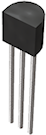
The Pinscape boards only use one package type, known as TO-92, which
looks like a little black half-cylinder about 5mm on a side, with
three leads sticking out the bottom.
Orientation
The TO-92 case is an industry-standard shape and size, but oddly, they
didn't standardize the order of the leads while they were at it. If
you want to figure out which lead is the base, which is the
collector, and which is the emitter, you have to look at the data
sheet for the part you're using. For example, if you look at the
data sheet for the 2N4401 transistor, it'll include a little diagram
like this:
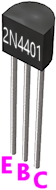
In the diagram, E = emitter, B = base, C = collector.
Other transistors in the exact same TO-92 package might have the
leads in a completely different order.
Even though they didn't standardize the lead order for the TO-92
package itself, they do always use the same lead order for
a given transistor. Every 2N4401 in a TO-92 case will use the
same lead order shown above.
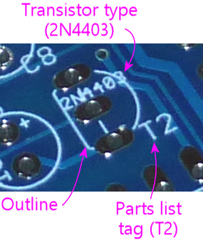
Printed circuit boards take advantage of that fixed lead order for
each specific transistor type to give you a handy orientation key for
each transistor, printed right on the circuit board. If you look at
the outline for any transistor in a TO-92 case, you'll see that the
outline (as usual) matches the shape of the transistor when you view
it from straight overhead. The outline has that same half-circle
shape with one side flattened. That flat side is the orientation key.
Just line up the flat side on the transistor with the flat side on the
printed outline.
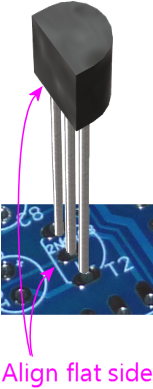
Installing in a circuit board
Orient the transistor to match outline printed on the circuit board as
shown above. Fit the three leads through the corresponding three
holes in the circuit board. Feed the leads through the board until
the part is seated as close to the board as you can comfortably get it
without forcing it.
Hold the part in place, flip the board over, and solder the three
leads to the solder pads. When the solder cools, snip the excess
length from the leads.
Selection
Transistors don't have a simple "unit" that describes them, the way we
have Ohms for resistors or Farads for capacitors. Instead, schematics
and parts lists will specify a particular transistor to use, by part
number.
Transistor part numbers starting with "2N" refer to common, generic
transistor types that are made by many manufacturers to the same
specs. Many other transistors are identified by a manufacturer's
proprietary part number. Manufacturer-specific part numbers don't
follow any particular standard format, as they're up to each company
to define.
In either case, use the part number listed in the schematic or parts
list to search for a matching part at Mouser or another vendor.
It's always best to use the exact part listed, but many transistors
have mutually compatible substitutes available. Try a Google search
for a term like "2N4401 equivalent" if you can't find the exact
original part specified.
All of the NPN and PNP transistors used in the Pinscape boards are
used for their switching function. That makes them largely
interchangeable with other transistors that are described as "small
signal transistors". If you can't find the exact option for a
transistor in the Pinscape parts list, you can probably substitute any
other "small signal transistor" that meets these requirements:
- It's the same basic type (NPN or PNP) as the original
- Its maximum collector current (IC, typically listed in the "Absolute Maximums" section of the data sheet) is at least as high as the value listed for the original part in its data sheet
- Its maximum emitter-base voltage (VEBO) is 12V or higher
- Its maximum collector-emitter voltage (VCEO) is 12V or higher
- It has the same case type (TO-92, TO-220, etc), to ensure that the leads will fit in the same solder pad holes in the circuit board
- Its leads (emitter, base, collector) are in the same order, so that you can plug it in the same way. (Alternatively, it can be in the reverse order, as long as you remember to rotate it 180° from the way it's depicted on the circuit board when installing it, to match the reversed lead order.)
Note that those rules are specifically for the Pinscape boards. If
you're trying to make similar substitutions for other circuit boards,
you should those specs for VEBO and VCEO from "12V
or higher" to "at least as high as the value listed on the original
part list". I was just trying to save you the trouble of looking
those up for the Pinscape parts, since in those cases you wouldn't
need specs higher than 12V.
Darlington transistors
A Darlington transistor isn't really a different type of transistor;
it's just a different kind of physical packaging. But it's worth
mentioning because it looks a little different on schematics.
A Darlington is a pair of NPN or PNP transistors, linked together
inside a single physical package. To the "outside world", it looks
and acts very much like a single NPN or PNP transistor. What makes
these devices useful is that the linkage of the two transistors
greatly increases the amplification power - the first transistor
amplifies the input signal, and the second transistor amplifies that
amplified signal, so it's like multiplying the two together. A
circuit designer can accomplish the exact same thing by wiring two
transistors together the same way, but this is such a common trope in
circuit design that it's convenient to have it available as a single
part. It's one less discrete part to install when you're building a
board.
On a schematic, a Darlington is drawn as a pair of regular transistors:
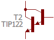
This schematic symbol is so similar to the symbols for two individual
transistors that it's kind of hard to distinguish whether it's a
single Darlington or two regular transistors. The tell-tale is that
there's only one reference designator and part number shown for the
pair. The other way you can tell (although less definitively) is that
the two individual transistor symbols are drawn so closely together,
with almost no "base" line in the second transistor symbol. If they
were were in fact meant to be discrete parts, they'd probably be
spaced out a little more.
Physically, a Darlington is just like a regular NPN or PNP. Like the
regular kind, it has three leads, labeled Base, Collector, and
Emitter. You install it in a circuit board just like the regular
kind of transistor.
