49. Pinscape Outputs Setup (Standalone KL25Z)
The standalone KL25Z (without the expansion boards) is capable of
controlling feedback devices such as LEDs, motors, and solenoids.
However, there are some important limitations you should be aware of:
- The GPIO pins on the KL25Z have extremely low power limits,
so you can't ever connect a feedback device directly to a GPIO pin.
All devices have to be connected through "booster" (amplifier)
circuits, which you have to build separately and connect to the KL25Z.
You really do need boosters for everything, even small LEDs,
because the GPIO power handling limits are simply too low to connect
anything directly.
There are several options for booster circuits that you can use for different types of devices. Full instructions are provided later in this section.
- The number of devices you can connect is limited by the number of available GPIO pins, because each output device requires its own dedicated GPIO pin. The KL25Z has about 50 GPIO pins in all, but remember that many of them will be needed for other purposes, such as button inputs and plunger sensor connections. In the default configuration, there are only about 20 pins available for feedback devices. You can change the pin assignments with the Config Tool, so you can take some pins that are assigned by default to other functions and reassign them as feedback outputs, but that will of course reduce the number of pins available for those other functions.
- The KL25Z only has 10 PWM channels. PWM is needed if you want to control the brightness of an LED or the speed of a motor; without PWM, a GPIO pin can only act as a simple on/off switch. 10 channels isn't enough for the standard five-flasher setup, since each RGB flasher needs three PWM channels (one each for red, green, and blue).
If you can live within these limits, the standalone KL25Z makes a
great output controller at low cost. If you need more outputs in
general or more PWM outputs in particular, you might want to consider
adding the Pinscape expansion boards - which were specifically
designed to overcome all of these limits - or one of the commercial
I/O controller devices. See Expansion Boards Overview for more on the
expansion boards, and I/O Controllers for a survey of
the commercial alternatives.
An additional option for adding more outputs, if you run out
of available GPIO pins, is to simply add a second KL25Z. The
Pinscape software is set up so that you can run multiple KL25Z's
in the same system.
Viewing and assigning output ports
Most of the GPIO pins on the KL25Z can be assigned to different
purposes using the Pinscape Config Tool. The default configuration
for a standalone KL25Z (without the expansion boards) assigns
22 pins as output devices, but you can add more output ports
by reassigning pins assigned to other purposes, such as button
inputs.
To view the list of ports currently assigned as output pins:
- Run the Pinscape Config Tool
- Go to the Settings page
- Scroll down to the Feedback device outputs section
That will show you a list of all of the pins assigned as output ports.
Each port has a port number, which is used to identify the port in the
DOF Config Tool. That port number is
just an abstract label, for DOF's sake, that doesn't mean anything in
terms of KL25Z hardware. To find the KL25Z hardware pin, scan across
the row to find the GPIO pin.
Each row also show a port type, which can be Digital Out or PWM Out.
Digital ports are simple on/off ports, with no ability to control
brightness or intensity. PWM ports can set different brightness
levels on the output, so they're best for LEDs and other lighting
devices. ("PWM" stands for "pulse width modulation", which means that
the port switches on and off very rapidly. The ratio of "on time" to
"off time" determines the effective brightness or intensity.) PWM
ports are also good for shaker motors and fans, since the intensity
control can be used to adjust the speed of the motor.
The KL25Z has an inherent hardware limit of 10 PWM ports. Further,
only certain pins (about 20 of them) have PWM capability at all.
There's no need to memorize which pins are which; the Config Tool's
pin assignment dialog always shows you the available pins of each
type.
A "Virtual" port is simply a port that's not connected to anything.
It still shows up over the USB connection, so DOF and other PC
software can access it as though it were actually there. But when DOF
sends it a command, it'll just harmlessly ignore the command. Virtual
ports let you satisfy DOF's expectations that a certain number of
ports are present even if you don't have enough physical GPIO pins
available for all of the ports DOF expects.
To add a new output port, go to the feedback device outputs
section as described above, then:
- Find one of the ports that's currently marked "Virtual". If there aren't any of those, click the "+" icon in the blank row at the very end of the list. That will add a new Virtual port.
- Click the pin assignment box (currently "Virtual") in the port row you want to assign. This will open a pin selector dialog.
- In the pin selector, click the type of port you want to add at the right (Digital Out or PWM Out).
- Select the GPIO pin you want to assign.
Important! A pin can only be assigned to one function at a time. The
dialog will allow you to select pins that are already assigned to
other functions, but if you do, the pin will show a little error icon
( ) next to the
pin. You must resolve any such warnings before the device will
work properly.
) next to the
pin. You must resolve any such warnings before the device will
work properly.
) next to the
pin. You must resolve any such warnings before the device will
work properly.
To determine what a pin warning means, simply click the warning icon.
This will pop up a dialog explaining what's wrong. The usual problem
is that you've assigned the same pin to two or more functions. That's
simply not workable at a hardware level, so you'll have to remove the
conflicting assignment(s). The warning message in the popup will tell
you exactly where the conflicting use is assigned. Go to the
appropriate section of the Settings page and remove that conflicting
assignment.
Wiring KL25Z outputs
The basic wiring plan for a KL25Z output looks like this:
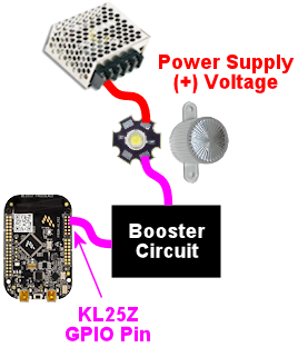
The complication is that little box labeled "booster circuit". That's
required because the KL25Z itself only allows a tiny, tiny amount of
current to flow through each GPIO pin. Too much current will damage
the KL25Z by overheating its delicate internal wiring.
The reason we show the booster circuit as a little box rather than
an electronic schematic is that you have multiple options for what
to put there. We'll look at some common options in a moment.
Note that the diagram above also leaves out other details specific to
the type of output device. For an LED, you'd need a current-limiting
resistor somewhere in the wiring; see LED Resistors. For a
coil, solenoid, motor, etc., you'd need a diode to protect against the
magnetic field effects; see Coil Diodes. See the descriptions
of the individual types of feedback devices for more details on each
one's special needs.
Remember, the exact KL25Z pins that correspond to output ports are
under your control! That's why we're not just printing a list here -
there is no fixed list to print. To find out what's currently
assigned in your setup, look at the Settings page in the Pinscape
Config Tool as described above.
NPN booster
This is a simple and inexpensive booster you can build for a low-power
device, up to about 600mA at 40V. That's enough for a small
incandescent lamp (e.g., a #555 bulb in a front-panel button), a
flasher LED, or a small relay.
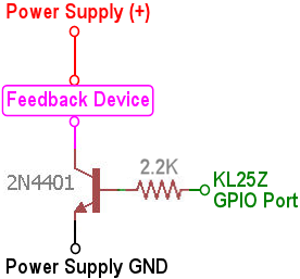
The power supply (+) and GND connections are meant to connect to the
secondary power supply that you're using for the feedback devices.
Note that you should provide a wire directly to the power supply
ground from the transistor's emitter, as shown, rather than connecting
it to a Ground pin on the KL25Z. The KL25Z ground pins ultimately do
all connect back to the power supply grounds, but they go through the
computer's USB port, which has limited current carrying capacity.
It's important to bypass that with a wire directly to the power supply
ground to avoid forcing too much power through the USB port.
The 2N4401 is a common transistor that should be easy to find, but
there's nothing magical about that particular part. There are
hundreds of similar "small signal transistors" that can be
substituted. Common substitutes: BC547, 2N3904, PN2222. If you do
substitute a different transistor, check its data sheet for the power
limits, since the limits quoted above (600mA, 40V) are specifically
for the 2N4401, and other transistors might have different limits.
The maximum values to look for in the data sheet are the "Absolute
Maximum" ratings for:
- Collector-Emitter Voltage (VCEO): maximum power supply voltage for the feedback device
- Collector current, continuous (IC): maximum feedback device current
Any ordinary 2.2K resistor will work. (The smallest resistors are
usually 1/8 Watt, which is perfectly fine for this job. Higher
wattage resistors will work as well but are unnecessary.)
DIY MOSFET booster
This is my go-to booster circuit. It's the one used in the Pinscape
power boards. It's versatile enough for just about anything you'd
want to put in a pin cab, including high-power toys like shaker motors
and replay knockers. The exact power limit depends on the specific
MOSFET you choose, but common MOSFETs are readily available that can
handle way more than you'd ever need, upwards of 10 or 20 Amps.
This circuit is more complex than the NPN booster above, but it's
still pretty simple - only five parts.
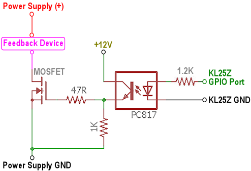
If you need help decoding the schematic, see A Crash Course in Electronics.
The resistor slots can all be filled with ordinary resistors with
the specified "Ohms" values. There's no special Wattage rating
needed for any of these.
Which MOSFET to use? Here's a list of parts I've tried that work
well:
- BUK7575-55A
- FQP13N06L
- FQP30N06L
But lots of other MOSFETs will work just as well. Any N-channel type
sold by an Arduino or robotics company will probably be suitable,
since robotics projects often use these parts exactly the same way we
do (and for the same reasons). If you want to cast a wider net by
looking on Mouser, the basic type of part you need is an N-channel
enhancement-mode MOSFET - but that turns up about 8,000 matches on
Mouser, so here are some more specific characteristics to look for:
- Low "on" resistance (RDS(on)), below 1Ω (preferably something like 100mΩ)
- Drain-source voltage (VDSS) sufficient for your feedback device power supply, preferably above 40V
- Continuous drain current (ID) sufficient for your feedback device's needs, preferably above 10A
- Through-hole package (for easier soldering)
Here's a Mouser search for those characteristics. This still matched
about 1,400 parts when I tried it, so it doesn't exactly narrow things
down to a trivial selection, but I'd sort by price, pick one of the
cheaper ones, and scan the data sheet to make sure it looks like a
suitable part for logic applications.
As with the NPN booster above, the power supply (+) and GND
connections are meant to connect to the secondary power supply that
you're using for the feedback devices. (Don't connect "Power Supply
GND" through a KL25Z Ground pin.)
If you're connecting a device with any sort of coil (including
solenoids, relays, contactors, and motors), be sure to use a diode
with the device, as explained in Coil Diodes.
Note: the old version 1 Pinscape Build Guide had a similar circuit
plan for a MOSFET booster, but that plan added a Darlington transistor
chip between the GPIO pin and the PC817. This newer version dispenses
with that extra chip. The purpose of the Darlington was to boost the
weak signal from the KL25Z to better drive the opto, because I was
concerned in the early days about the optos being sensitive enough for
the KL25Z to drive them directly. Experience has shown that the extra
boost isn't needed, so I've simplified the circuit plan to remove the
unnecessary extra part. The older plan will still work just fine,
too, it's just more complicated than it has to be.
Pre-built MOSFET booster
Thanks to the popularity of Arduinos and hobby robotics, you can buy
pre-built boards that implement roughly the same circuit as the DIY
MOSFET booster above.
There's no name-brand board or seller that I can point you to,
unfortunately. The boards I've seen are sold on eBay and
Aliexpress.com, so the sellers are small shops that come and go. If I
gave you a link here, it would probably be gone by the time you tried
it. So instead I'll tell you what to search for on those sites: try
something like "Four channel MOSFET board".
Most boards like this will have a very similar design to the DIY
MOFSET circuit shown above. The one big difference will be that the
resistor between the signal input terminal (where you connect the
KL25Z GPIO pin) and the optocoupler will typically be smaller than the
one in the DIY circuit. That's because generic boards like this will
always be intended for use with an Arduino, which has much higher
power capacity on its GPIO pins that the KL25Z does.
So I recommend the following procedure:
- Set up the board as recommended by the manufacturer, but add a 1K resistor between the KL25Z GPIO pin and the input terminal on the board.
- Test it (with the Pinscape Config Tool's output tester, for example) to see if the output turns on as expected. If so, you're done!
- If it doesn't turn on, try removing the 1K resistor and replacing it with a 680Ω resistor. Repeat the test. If it works, great; if not, drop to 470Ω and try again.
The point of the extra resistor is to reduce the current on the GPIO
port to a safe level for the KL25Z. The KL25Z has a maximum limit of
4mA per port. These boards are usually designed to work at
about 20mA, because the Arduino can tolerate the higher current.
If you have a multimeter, you can test the actual current being drawn
on the port to verify that it's within the safe range, below 4mA. You
can try resistors below 470Ω if necessary, but if you do you
should measure the current to verify that it's not too high.
Sainsmart booster
There's a non-USB version of the Sainsmart relay boards, designed
mostly for Arduino users, that can be be used with the KL25Z. Some
people using the Pinscape software have successfully used that as a
booster. However, I don't recommend it, because I've heard too many
bad things about reliability. The relays reportedly have a short
lifetime (weeks or months) when used in a pin cab. The transistor
solutions above are much more reliable, and probably cheaper.
LED strip mini amplifier
If you search on eBay for "LED strip mini amplifier", you'll find
products that look like this:
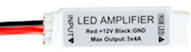
Some people have used these successfully with the KL25Z as a power
booster circuit. However, I don't recommend doing this, because some
of these devices are electrically incompatible with the KL25Z and can
damage it if attached directly. It's difficult to tell whether a
given mini-amp is safe to use with the KL25Z, so my advice is simply
to avoid them entirely.
Testing and troubleshooting
The best way to test your connections is using the Pinscape Config Tool:
- Make sure all of the wiring is in place for the feedback device you want to test
- Run the Config Tool
- Click on the Output Tester button
- Find the port you want to test in the list
- For a PWM port, use the slider to test the brightness control. For a digital out port, use the ON/OFF button to test it.
The output tester sends commands directly to the KL25Z via the USB
connection, so it bypasses other software layers (such as DOF and VPinMAME).
If a port is working in the output tester, you can be confident that the
hardware and wiring is all working correctly, and that any problems
you're having with it in Visual Pinball or other programs are purely
software configuration issues. If a port isn't working in the
output tester, the problem is probably in the wiring or in the
feedback device itself.
Voltmeter tests
You can do some simple testing with a voltmeter to confirm that the
KL25Z is sending the right signal to the GPIO pins.
This test has to be done with the power on, so be careful! Make sure
that you only touch the meter's probes to the pins you want to test,
and that you don't short together adjacent pins. The pins are closely
spaced, so you have to be really careful about this.
- Disconnect the output from the GPIO pin you want to test (including both the feedback device and the booster circuit)
- Power up the system
- Run the Pinscape Config Tool
- Click on the Output Tester button
- Set your meter to DC Volts
- Connect the meter's black probe to one of the KL25Z's ground (GND) pins, or to any convenient ground connection to your power supplies. (Remember that all of the grounds should be interconnected, as described in Power Supplies for Feedback, so any of these points should be equivalent.)
- Connect the meter's red probe to the GPIO pin you want to test
- When the port is off in the output tester, it should read close to 0V (exception: an Active-Low port should read close to 3.3V)
- When the port is on in the output tester, it should read close to 3.3V (exception: an Active-Low port should read close to 0V)
If this test passes, your KL25Z is working correctly, and the software
is configured properly so that the software port is connected to the
physical GPIO pin. Any problems must be in the wiring to the booster
circuit and/or to the feedback device.
If this test fails, either your KL25Z hardware is broken, or you have
a problem with the software configuration. Check carefully that the
pin you're looking at in the output tester matches the physical pin
that you're testing on the KL25Z. Look very closely - make sure that
you don't have the KL25Z flipped upside-down, for example, since that
would make all of the pins in the mirror-image locations from where
you think they are.
DOF Setup
To set up your standalone Pinscape device with DOF, you of course have to
install DOF on your PC first. See DOF Setup for instructions.
Once the DOF software is installed, you use the
DOF Config Tool to tell DOF that
you have a Pinscape unit, and to tell it which KL25Z pins are
attached to which output devices.
- Open the DOF Config Tool in your browser
- Click the My Account tab
- Set Number of Pinscape devices to 1 (or if you have more than one KL25Z running the Pinscape, select the appropriate number of devices instead)
- Set Number of KL25Z devices to 0 (see below if this seems confusing)
- Save changes
- Go to the Port Assignments page
- Select "Pinscape 1" in the Device drop list
- Go through the port list, assigning each port number in the DOF list to the device that you wired to that port on the KL25Z
The port list in the Port Assignments page uses the same port
numbering (Port 1, Port 2, etc) that's shown in the Pinscape Config
Tool output port list. This isn't the GPIO port name or
physical pin number on the KL25Z. It's just the abstract port
number from the output port assignment list.
To figure out what DOF's "Port 1" or "Port 2" means in terms of the
physical GPIO pin on the KL25Z, you have to look at the output port
list in the Pinscape Config Tool's Settings page. In the output list,
find the same port number shown in DOF - if you're looking for DOF's
"Port 1", you want the first row, #1, in the Pinscape output list.
Trace across the row to find the KL25Z port name and pin. If you want
to see a picture of where that pin is physically located on the KL25Z,
click the pin name in the row - that will pop up the pin selector,
which will show the pin location highlighted on a picture of the
KL25Z.
Using two (or more) KL25Zs
If you like the idea of using a standalone KL25Z as your output
controller, but you need more ports, there's an easy solution: add a
second KL25Z. Or even a third or fourth. Additional units give
you more output ports - and on secondary units, you don't even have
to share GPIO pins with other functions like buttons and plungers.
You only need those input pins on the first KL25Z unit, so nearly
all of the pins on secondary units can be reassigned as outputs.
The Pinscape software is set up so that you can have up to 16 separate
KL25Z units in your system. The only additional setup work required
to add a second KL25Z is to give it a unique ID, using the Pinscape
Config Tool:
- Detach all of your other KL25Z units
- Attach the new one you want to program with a new ID
- Run the Pinscape Config tool
- Go to the Settings page for the unit
- In the USB ID section, set the ID to LedWiz Unit 9
- In the Pinscape ID section, set the ID to Pinscape Unit 2
- In the Joystick section, un-check the "Enable joystick input" box
Repeat this process for each additional KL25Z, advancing to the
next LedWiz Unit number and Pinscape Unit number for each additional
device.
(The USB ID doesn't actually have to be an LedWiz unit number at all,
and doesn't have to be in this exact order. That's just the
recommended order for the widest software compatibility. You should,
however, use Pinscape unit numbers 1, 2, and so on, in that order.
The DOF Config Tool is difficult to set up otherwise.)
Why disable the joystick input? Because you want to make sure that
only one of the KL25Z units is sending accelerometer (nudge) readings
to the PC. Pinscape sends those readings by default, so you have to
turn off the readings in all of your secondary units to avoid
confusing the PC with a barrage of different information from
different units.
DOF setup: To set up a second Pinscape unit with DOF:
- Open the DOF Config Tool in your browser
- Click the My Account tab
- Change the "Number of Pinscape devices" to the appropriate number
- Save changes
- Go the Port Assignments page
- Select "Pinscape 2" in the Device drop list
- Set up the ports for the devices attached to the second KL25Z
- Repeat for additional units
The online DOF Config Tool has a confusing bit of terminology in the device setup section on the "My Account" page. In the list of devices, you'll find separate entries for "Number of Pinscape devices" and "Number of KL25Z devices".
For Pinscape boards, use only the Pinscape devices option. Always leave "Number of KL25Z devices" set to zero (0). This applies whether you're using the expansion boards or a standalone KL25Z.
This is confusing because the Pinscape software does happen to run physically on a KL25Z board, so it might seem like you should enter the same number for both line items. Don't. Pretend that you've never heard of a KL25Z and that you have zero of them.
The Config Tool has the "KL25Z devices" line item for historical reasons that date back to the first version of the Pinscape software, when it was limited to 32 output ports. It should more properly be titled "Number of Pinscape v1 devices", because that's what it really means. In any case, just ignore it and leave it set to zero.
