50. LedWiz Setup
The LedWiz has long been the most popular output controller for
virtual cab builders. It was originally created for video game
cabinets, not for pin cabs, but the two have a lot in common: they
both use a PC to run their software, and they both use arcade controls
built into a custom enclosure. Video game cabs use the LedWiz mostly
to control button lamps and other cabinet lights. But a device like
the LedWiz that can turn lights on and off can really turn just about
anything on and off, so it filled the need when early pin cab builders
wanted to install mechanical force feedback devices in addition to
lights.
The LedWiz has a lot of virtues. It's inexpensive, it has a
"driverless" software design that makes it practically effortless to
set up in Windows, it has lots of output ports (32), and it has the
ability to control the brightness on all ports via PWM. Its only
serious limitation is power handling.
Power limits and boosters
The LedWiz has fairly low power limits, because of its legacy as a
video game device. In a video game cab, the only "feedback" devices
most people install are small light bulbs and LEDs. The LedWiz's
designers chose the power limits accordingly.
The exact limit is 500mA per output port. (To be really technical,
there's also a limit on the combined power across groups of ports, but
we can mostly ignore that in a pin cab; that only applies if all of
the ports are switched on for long periods at the same time, which
essentially never happens in a pin cab.)
500mA is plenty for the light bulbs and LEDs that the LedWiz's
designers had in mind. But it's not enough for some of the mechanical
devices we use in pin cabs. Many types of solenoids, contactors,
coils, and motors can greatly exceed this. Some high-power LEDs can
exceed it, too. So whatever you're connecting, be sure you know how
much current it uses, and be sure it's safely under the 500mA limit.
If you can't find information on a device's power usage in its
instructions or spec sheet, you can measure it with a multimeter set
to Current (Amps) mode.
What should you do if a device exceeds the 500mA limit? Well, for
starters, don't connect it directly to the LedWiz. If you do,
you'll likely destroy at least the one LedWiz port that you connected
the device to, and possibly a whole group of eight ports (because each
group of eight ports is controlled by a single chip on the LedWiz, and
an overload on one port can destroy the whole chip).
What you need in this case is a "booster" circuit of some kind. A
booster is something that increases the power handling on a port,
which it accomplishes by adding a second electronic switch between the
LedWiz and your high-power feedback device. The LedWiz controls the
booster's second switch, and the second switch controls the feedback
device.
Here are the main types of boosters you can use:
- A booster board from zebsboards.com. Zeb's sells several boards that connect to an LedWiz. These use high-power transistor switches, so they're compatible with PWM brightness control. This is the easiest option, because Zeb's products are built specifically for virtual pin cab use, so you won't have to improvise anything to fit them into your system.
- Your own DIY booster circuit using a MOSFET or other transistor. We provide a simple circuit design below. It's easy to build, and it's powerful enough for just about any type of pin cab device.
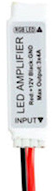 An LED light strip
amplifier from eBay. Search for "Mini LED amplifier", and look for
products similar to the one pictured at right; they go for about $1
apiece if you buy a lot of 5 or so. These use transistor switches
based on the same principles as Zeb's boosters or the DIY booster
circuits described above. These are designed to be used with RGB
light strips, so each unit has three independent channels of
amplification, so you'd need 11 of them to boost all 32 ports on an
LedWiz. Each channel can typically handle 4A, which is enough for
most pin cab devices. The main drawback with these is that it you'll
have to improvise a bit to wire them, since they're physically
designed to mate with the common LED strips.
An LED light strip
amplifier from eBay. Search for "Mini LED amplifier", and look for
products similar to the one pictured at right; they go for about $1
apiece if you buy a lot of 5 or so. These use transistor switches
based on the same principles as Zeb's boosters or the DIY booster
circuits described above. These are designed to be used with RGB
light strips, so each unit has three independent channels of
amplification, so you'd need 11 of them to boost all 32 ports on an
LedWiz. Each channel can typically handle 4A, which is enough for
most pin cab devices. The main drawback with these is that it you'll
have to improvise a bit to wire them, since they're physically
designed to mate with the common LED strips.
- Individual relays. A relay is a mechanical switch controlled by an electromagnet. Normally, the switch is disconnected ("open"). When the magnet is energized, the switch "closes", connecting the attached wires. To use a relay as an LedWiz booster, you connect the relay coil to the LedWiz as though it were the feedback device; that lets the LedWiz turn the relay switch on and off according to the port status. You then connect the actual feedback device to the relay switch. When the LedWiz turns the port on, it energizes the relay, closing the switch and connecting power to your feedback devices. This is fairly easy to set up, and you can find relays that can handle enough power for large devices. The downside is that a relay can't handle PWM for brightness control, so it's not good for lights, and also doesn't work for motors if you want variable speed control.
- A SainSmart relay board (the non-USB type). SainSmart sells boards
with different numbers of relays (from 1 to 16) that can be controlled
by a device like the LedWiz. This is the same idea as using an
individual relay as described above, but the SainSmart boards make it
a little more convenient if you want to boost multiple outputs this
way. As with individual relays, the SainSmart relays can't handle
PWM, so they're not great for lights or adjustable-speed motors.
Note that SainSmart sells two completely different kinds of relay boards: USB and non-USB. For an LedWiz booster, you want the non-USB type, also known as an "Arduino module", since they're sold primarily to Arduino users. Don't get the USB type for this use case, since that's a standalone controller that you'd use instead of an LedWiz.
What about the "H-bridge hack" I've read about for motors?
Back in the early days of pin cabs, someone came up with the idea of
hacking into the LedWiz's internal wiring to connect a special type of
booster circuit known as an H-bridge. The idea came from the Arduino
robotics world, where H-bridges are often used to control robot wheel
motors from Arduino GPIO ports. Someone in the pin cab world must
have read about it and thought that "H-bridge" and "motor" just
naturally go together, and the idea made its way into the forums and
got repeated a lot. But you actually don't need an H-bridge to
control any of the common virtual pinball motor devices.
The special feature of an H-bridge is that it can be boost both
positive and negative input voltages. That's useful with robot motors
because it lets you run the motor bidirectionally. But in a pin cab,
we have no need to run our motors in reverse. The motor devices
we use - shakers, gear motors, fans, beacons - only need to run in
one direction.
So in a pin cab, you don't need an H-bridge for your motor
devices. You just need one of the general-purpose boosters we cover
here. The only special requirement is to make sure the booster you
choose has a high enough current limit for your motor. Shaker motors
and windshield wiper motors (if that's what you're using for your gear
motor) run at about 4A, while fan motors and beacons are typically
more like 1A to 2A. The generic DIY MOSFET circuit described later in
this section can easily handle any of those loads.
Note that you could use an H-bridge if you really wanted to, but
there's no benefit, and they're more complex and expensive to set up
than a standard booster circuit. And the H-bridge "hack" for the
LedWiz is actively harmful. The "hack" requires you to modify your
LedWiz by soldering a wire onto a tiny pin on one of the LedWiz's
surface-mount IC chips. It's a difficult soldering job because of the
small pins involved, and it runs the risk of damaging the device.
So I'd definitely ignore the whole H-bridge idea and use one
of the simpler booster options instead.
Connecting the LedWiz to the PC
Connecting the LedWiz to the PC requires two bits of wiring.
First, you'll need some insulated hookup wire. (I'd recommend 22 AWG,
but anywhere from 16 AWG to 24 AWG is fine.) Connect one end to the
External Ground terminal on the LedWiz, which is labeled G (for
Ground) and should be near the USB connector. Connect the other end
of the wire to an unused disk power connector on your PC power supply
or a secondary ATX power supply. Be sure to connect to one
of the black wires in the disk connector.
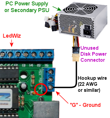
Connecting the LedWiz ground terminal. Use
ordinary hookup wire (around 22 AWG) to connect the G terminal
on the LedWiz to the black wire in an unused disk power connector on
your power supply. The LedWiz comes in a couple of versions, so yours
might not look exactly like the photo, but there should still be a
similar G terminal.
For more on connecting power wires to the PC power supply, including
how to build your own connectors, see Power Supplies for Feedback.
Second, plug a USB cable into the USB connector on the LedWiz, and
plug the other end into a free USB port on your PC.
Positive power supply connections
Some versions of the LedWiz have a set of terminals for connecting the
positive (+) voltage from your power supply. You should simply
ignore these and leave them unconnected. These inputs are
unnecessary as long as you use your own diodes for any
attached coils or motors, and they complicate the wiring if you do use
them. It's best to use your own diodes and ignore these inputs.
The function these inputs serve is to connect some internal diodes
within the LedWiz chips across the output port terminals. The diodes
are meant to provide a degree of protection against power spikes from
inductive devices. That protection is important, but you can get
better protection by installing your own external diodes, as explained
in Coil Diodes. Doing that will make the internal diodes
redundant, allowing you to leave the LedWiz voltage inputs
unconnected.
Basic device wiring plan
Before connecting anything to the LedWiz, please make sure its power
draw is safely below the LedWiz's limit of 500mA per output. Any
device that draws more power requires a booster circuit; see
Power limits and boosters above.
Attaching a device that draws too much power can damage or destroy
the LedWiz.
The basic feedback device wiring plan for an LedWiz is pretty simple:
- All of the "-" or "Ground" connections from all of your power supplies should be connected together (see Power Supplies for Feedback)
- Connect the "+" terminal from the power supply directly to the "+" terminal on the feedback device
- Connect the "-" terminal on the feedback device to one of the numbered LedWiz terminals
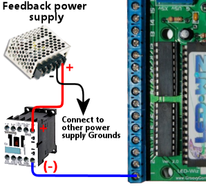
The LedWiz acts like an electronic switch that connects and
disconnects the "-" side of a device to the power supply. The LedWiz
can only switch the "-" side, so it's important to wire the
polarities exactly as described above.
Some feedback devices aren't polarized, meaning they don't care which
power input is "+" and which is "-". This is true for most coil
devices, like solenoids and relays, as well as for incandescent lamps.
If the device doesn't have "+" and "-" markings for its power
terminals, simply follow the same wiring plan shown above, but you can
attach the wires to the feedback device itself in either order.
Some devices have special requirements beyond the basic diagram shown
above. For example, anything with a coil needs a diode (see
Coil Diodes), and most LEDs require current-limiting resistors
(see Flashers and Strobes). We go into more detail about each of the
popular pin cab devices in Feedback Devices.
Use protective diodes if necessary
Most mechanical devices require protective diodes. These
are required for anything with a coil: solenoids, contactors,
replay knockers, motors.
See Coil Diodes for details on what type of diodes to use
and how to install them.
Diodes are critical! Coils and motors can damage your PC motherboard
and other components if diodes aren't used.
Fuses
Many cab builders include a fuse in each LedWiz output circuit. This
isn't strictly necessary, but I think it's a good idea with the LedWiz
because of its low power limits. Fuses can help protect the LedWiz
from overloads caused by wiring faults and device malfunctions,
reducing the chance that the LedWiz will be damaged if something like
that goes wrong. See Fuses for details.
Windows setup
The LedWiz requires absolutely no Windows hardware drivers. It's
completely plug-and-play.
Visual Pinball and PinballX access the LedWiz through DOF, so you'll
need to set up DOF as described below.
LedWiz.dll
Some older software, such as Future Pinball, accesses the LedWiz
through a "DLL" file (a Windows "dynamic link library") called
ledwiz.dll. You can download this from the manufacturer's Web site
(GroovyGameGear.com), but I recommend
using my upgraded, open-source version instead. You can find
it here: DOF R3 &
LEDWIZ.DLL updates. My version works more reliably than the
official DLL, because it has special logic to work around some
recently discovered hardware bugs on the LedWiz itself.
LedWiz.dll should generally be installed in the same directory as each
program that uses it (e.g., Future Pinball). You might need to
install multiple copies if you're using multiple programs that
use the DLL.
You don't need ledwiz.dll for Visual Pinball, DOF, or
PinballX.
DOF setup
DOF is required to use your LedWiz with Visual Pinball and
PinballX. If you haven't already installed DOF on your system, follow the
instructions in DOF Setup.
Once you have the DOF software installed on your PC, follow
these steps:
- Point your browser to the DOF config tool
- Click the My Account tab
- Find "Number of LedWiz Devices" in the list, and set it to "1" (or to the number of LedWiz units you've installed, if more than one)
- Click Save Settings
- Click the Port Assignments tab
- In the "Device" drop-down, select "LedWiz 1"
- Go through the port list (Port 1 through Port 32), and select the type of device that you've physically wired to each output port. The port numbers in the list correspond to the numbers printed on the LedWiz board next to the screw terminals for the ports.
- Click Save Config
- If you have more than one LedWiz, repeat the process for each device by selecting the devices one at a time in the "Device" drop-down at the top of the page
- When done, click Save Config, then click Generate Config to download your updated DOF config files
- Unzip the downloaded files into your DOF install folder
All of this is described in the DOF Setup section as well.
Power boosters
Let's look at how to use the various booster options with
an LedWiz, in case you need more power for devices that
exceed the limit of 500mA per output.
Zeb's boards boosters
If you're using a booster board from Zeb's boards, see the wiring
plans included in the instructions that come with the board.
DIY booster circuit
Here's a circuit plan for a generic booster circuit that you can build
yourself with a few components. This is basically the same circuit
used in the Pinscape expansion boards. It's a great general-purpose,
high-power booster circuit that can drive just about anything in a pin
cab, from motors and solenoids to flashers and button lamps. This
circuit is fully compatible with the LedWiz's PWM dimming control.
The power limit for the attached device is determined by the type of
MOSFET you choose. The MOSFETs listed below can all handle upwards of
10 Amps, which is plenty for just about any pin cab device. (Shaker
and gear motors typically run at around 3A to 4A, and large pinball
solenoids like knocker coils need about 4A. All of the other common
devices have much lower power needs.)
Here's the circuit plan:
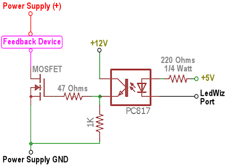
If you need help decoding the schematic, see A Crash Course in Electronics.
The resistors can all be filled with any ordinary resistor of the
specified "Ohms" size, except for the 220Ω resistor, which should
have a power rating of 1/4 Watt or higher. (You can always use a
higher wattage than specified with resistors.)
Which MOSFET to use? Here's a list of parts I've tried that work
well:
- BUK7575-55A
- FQP13N06L
- FQP30N06L
But lots of other MOSFETs will work just as well. Any N-channel type
sold by an Arduino or robotics company will probably be suitable,
since robotics projects often use these parts exactly the same way we
do (and for the same reasons). If you want to cast a wider net by
looking on Mouser, the basic type of part you need is an N-channel
enhancement-mode MOSFET - but that turns up about 8,000 matches on
Mouser, so here are some more specific characteristics to look for:
- Low "on" resistance (RDS(on)), below 1Ω (preferably something like 100mΩ)
- Drain-source voltage (VDSS) sufficient for your feedback device power supply, preferably above 40V
- Continuous drain current (ID) sufficient for your feedback device's needs, preferably above 10A
- Through-hole package (for easier soldering)
Here's a Mouser search for those characteristics. This still matched
about 1,400 parts when I tried it, so it doesn't exactly narrow things
down to a trivial selection, but I'd sort by price, pick one of the
cheaper ones, and scan the data sheet to make sure it looks like a
suitable part for logic applications.
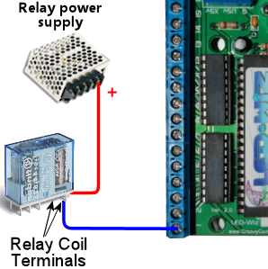
Individual relay booster
The idea here is to connect the relay coil to the LedWiz as though
it were the feedback device. So you connect the coil exactly
as you would any other device.
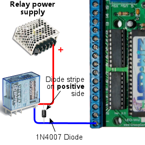
 You must also connect a protective diode across the coil's terminals,
to suppress the voltage spike that the coil will produce when it
switches off. A 1N4007 diode is a good general-purpose diode that you
can use for this. See Coil Diodes for full details.
You must also connect a protective diode across the coil's terminals,
to suppress the voltage spike that the coil will produce when it
switches off. A 1N4007 diode is a good general-purpose diode that you
can use for this. See Coil Diodes for full details.
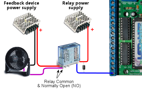
 Then you connect the actual feedback device to the relay's switch
terminals. Most relays are of the "double-throw" type, meaning
they have three switch terminals: common, normally open (NO), and
normally closed (NC). You connect the device to the common and
normally open terminals.
Then you connect the actual feedback device to the relay's switch
terminals. Most relays are of the "double-throw" type, meaning
they have three switch terminals: common, normally open (NO), and
normally closed (NC). You connect the device to the common and
normally open terminals.
 When shopping for a relay, pay attention to two important
specifications. First, make sure its coil current is safely
below the LedWiz's 500mA limit. Most small relays are well within
this, but some larger relays require more current. Second, make sure
that its switching load limits are above the voltage and current
required by the feedback device you intend to attach. Pay particular
attention the VDC (Volts DC) number and make sure it's above
the power supply voltage for the feedback device. Maximum DC
switching voltages are usually much lower for relays than their AC
switching voltages because DC voltage creates arcs more easily in the
switch contacts, so you might see a relay rated for 250VAC but only
30VDC.
When shopping for a relay, pay attention to two important
specifications. First, make sure its coil current is safely
below the LedWiz's 500mA limit. Most small relays are well within
this, but some larger relays require more current. Second, make sure
that its switching load limits are above the voltage and current
required by the feedback device you intend to attach. Pay particular
attention the VDC (Volts DC) number and make sure it's above
the power supply voltage for the feedback device. Maximum DC
switching voltages are usually much lower for relays than their AC
switching voltages because DC voltage creates arcs more easily in the
switch contacts, so you might see a relay rated for 250VAC but only
30VDC.
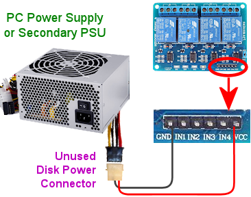
SainSmart relay board as a booster
Start by connecting the relay board to the power supply. Find the
pins labeled GND and VCC, and connect these to your PC
power supply (or secondary ATX power supply), using an unused disk
connector. Connect GND to the power supply black wire. The SainSmart
boards come in 5V and 12V versions. If you have a 5V version, connect
VCC to the red power supply wire; for the 12V version, connect VCC to
the yellow power supply wire.
 SainSmart relay board power hookups. Connect
the SainSmart GND pin to the black wire in a disk power cable
from the PC power supply. Connect the Sainsmart VCC pin to the
red wire if you have a 5V board, or the yellow wire if it's a 12V board.
Next, connect the relay board's input pins to the LedWiz output ports.
Find the pins labeled IN1, IN2, etc. These are the inputs.
IN1 is the input for the first relay, usually labeled
K1, and the other inputs correspond to the other relays the
same way. Connect a wire between each INx pin and an LedWiz
output port terminal.
SainSmart relay board power hookups. Connect
the SainSmart GND pin to the black wire in a disk power cable
from the PC power supply. Connect the Sainsmart VCC pin to the
red wire if you have a 5V board, or the yellow wire if it's a 12V board.
Next, connect the relay board's input pins to the LedWiz output ports.
Find the pins labeled IN1, IN2, etc. These are the inputs.
IN1 is the input for the first relay, usually labeled
K1, and the other inputs correspond to the other relays the
same way. Connect a wire between each INx pin and an LedWiz
output port terminal.
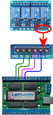 Note that the choice of four LedWiz ports shown in the diagram is
arbitrary, purely for the sake of illustration. You can connect any
other ports instead, and they don't have to be adjacent as shown.
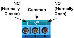
Finally, connect the output devices. Each relay has three terminals,
and you need to identify the Common and Normally Open
connections. The markings vary by board. You might see the legends
NC, C, and NO printed on the board next to the
terminals. These stand for Normally Closed, Common, and Normally
Open. You might instead see a little line diagram like this:
Note that the choice of four LedWiz ports shown in the diagram is
arbitrary, purely for the sake of illustration. You can connect any
other ports instead, and they don't have to be adjacent as shown.
Finally, connect the output devices. Each relay has three terminals,
and you need to identify the Common and Normally Open
connections. The markings vary by board. You might see the legends
NC, C, and NO printed on the board next to the
terminals. These stand for Normally Closed, Common, and Normally
Open. You might instead see a little line diagram like this:
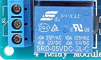
 If you can't find any markings, look for the set of three terminals
nearest the relay. The Common is almost always the center terminal,
and the Normally Open is usually the top terminal when the relay is
oriented like this:
If you can't find any markings, look for the set of three terminals
nearest the relay. The Common is almost always the center terminal,
and the Normally Open is usually the top terminal when the relay is
oriented like this:
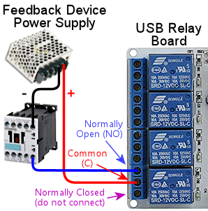
 Once you identify the Common and Normally Open terminals for the
relay, connect your feedback device like this:
Once you identify the Common and Normally Open terminals for the
relay, connect your feedback device like this:
LED amplifier as a booster
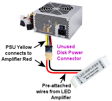
First, connect the LED amplifier to the power supply. You need a 12V
power supply for this; you can use a PC ATX power supply, preferably a
secondary unit rather than the one that's powering your PC
motherboard. Use the yellow and black wires for 12V.
The amp should have a pair of wires attached, one red and one black.
Red connects to +12V, black connects to the power supply ground.
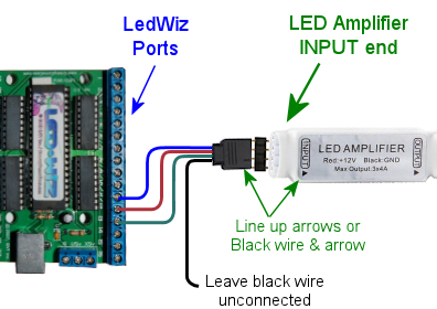
 Next, connect the LED amplifier to the LedWiz output ports. Run a wire
from each of the three Input pins on the amplifier to a port
terminal on the LedWiz. Don't connect the amplifier pin labeled
"+" or ▶.
The inputs and outputs on these amplifiers are designed to mate with
special 4-pin connectors. They're basically just thick wires, so you
might be able to improvise something, but the easiest approach is to
buy some of the special connectors. These can be found on eBay:
search for "LED male connector". The easiest ones to work with,
in my opinion, are this type:
Next, connect the LED amplifier to the LedWiz output ports. Run a wire
from each of the three Input pins on the amplifier to a port
terminal on the LedWiz. Don't connect the amplifier pin labeled
"+" or ▶.
The inputs and outputs on these amplifiers are designed to mate with
special 4-pin connectors. They're basically just thick wires, so you
might be able to improvise something, but the easiest approach is to
buy some of the special connectors. These can be found on eBay:
search for "LED male connector". The easiest ones to work with,
in my opinion, are this type:
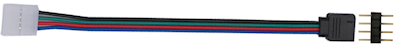 I like these because they use plain wires between the connectors, so
you can cut off the LED strip connector (the white connector in the
type pictures above) and be left with four wires that you can easily
attach to other types of terminals, such as the LedWiz terminals.
Using that type of connector, the connection to the LedWiz looks
like this:
I like these because they use plain wires between the connectors, so
you can cut off the LED strip connector (the white connector in the
type pictures above) and be left with four wires that you can easily
attach to other types of terminals, such as the LedWiz terminals.
Using that type of connector, the connection to the LedWiz looks
like this:
 Note that the specific ports shown in the diagram are arbitrary. You
can connect any three ports to each amp, and they don't have to be
adjacent. But I'd try to keep things organized cleanly anyway, for
your own, so that you can follow your wiring more easily when you come
back to it later.
Finally, connect the feedback device to the amplifier. Wire the
feedback device's "+" terminal to the power supply "+", and wire the
device's "-" terminal to one of the three Output pins on the
amplifier. The output pins are the same form factor as the input
pins, so you can use the same kind of connector described above
to connect these.
Note that the specific ports shown in the diagram are arbitrary. You
can connect any three ports to each amp, and they don't have to be
adjacent. But I'd try to keep things organized cleanly anyway, for
your own, so that you can follow your wiring more easily when you come
back to it later.
Finally, connect the feedback device to the amplifier. Wire the
feedback device's "+" terminal to the power supply "+", and wire the
device's "-" terminal to one of the three Output pins on the
amplifier. The output pins are the same form factor as the input
pins, so you can use the same kind of connector described above
to connect these.
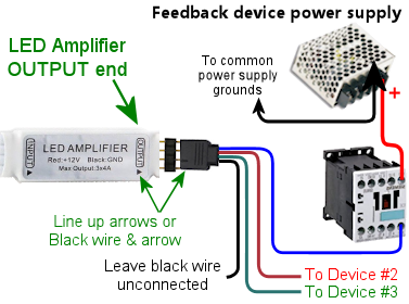 Note that each output pin on the amplifier corresponds to the input
pin across the case from it. You can use that to determine which
LedWiz port controls which output.
Note that each output pin on the amplifier corresponds to the input
pin across the case from it. You can use that to determine which
LedWiz port controls which output.
Using multiple LedWiz's
You can use more than one LedWiz in the same system, but there's a
slight catch: when you buy the second or third or Nth LedWiz, you have
to special-order it as the second or third or Nth device.
The reason this is necessary is that each LedWiz unit has a built-in
hardware ID that it uses to communicate with Windows over the USB
wire. The LedWiz documentation calls this the "device number" or
"unit number". This can only be set at the factory, so you have to
specifically order each device with a different unit number. If you
don't specifically ask, the unit number is usually "1". So if you want
to connect a second LedWiz to your system, you have to make a special
request for "unit number 2" when you buy the second one. If you want
to connect three, ask for "unit number 3" when you buy the third one.
And so on.
If you buy directly from the manufacturer,
GroovyGameGear.com, look
for the "Choose device number" area on the ordering page,
and enter the device number you need.
If you buy from eBay or another seller, you'll be stuck with whatever
unit number was set at the factory. That's completely fine if you
only need one LedWiz in your whole system. But if you want to connect
more than one, you'll have to order each unit with a different device
number, so you should order from someone who lets you specify this
when ordering.
SainSmart relay board power hookups. Connect
the SainSmart GND pin to the black wire in a disk power cable
from the PC power supply. Connect the Sainsmart VCC pin to the
red wire if you have a 5V board, or the yellow wire if it's a 12V board.
