88. KL25Z Hardware Setup
The KL25Z comes fully assembled and ready to use. All you have to do
to get it working is plug it into your computer with a USB cable.
If you're going to connect any additional hardware to the KL25Z
(plunger, buttons, feedback devices), there is one bit of additional
hardware assembly you'll have to do. You'll need to install "pins"
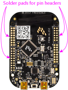
for plugging in connectors to the other devices. They don't install
these at the factory; they just include empty solder pads where you
can install your own pin headers if you wish to.
The KL25Z will run happily without the headers installed, so you
don't have to do this right now. You can skip ahead to the
software setup, and come back
here later, if you want to try out the board first.
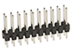
The specific headers to buy (along with the mating connectors, known
as "crimp pin housings") are listed in the "KL25Z Microcontroller
(Standalone)" section in Electronic Parts List.
They look like this on their own:
The installation procedure is a little different depending on
whether you're using the KL25Z "standalone" or with the Pinscape
expansion boards. Continue to the appropriate section below.
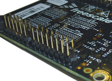
Standalone KL25Z pin headers
If you're using the KL25Z without the Pinscape expansion
boards, the pin headers go on the top side of the KL25Z - the side
with the large CPU chip and the USB connectors. Here's how they look
when installed:
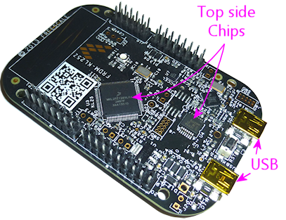
Important! Install the pins on the top as shown only for
standalone use, not for the expansion boards. The expansion
boards require the pins to be installed on the bottom side of the
board instead.
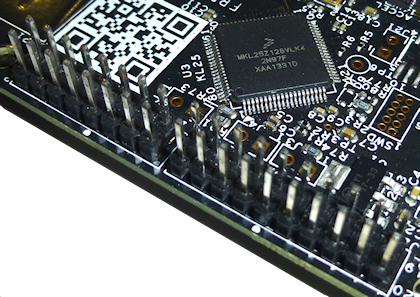
The pin headers are pretty easy to install:
- Fit the headers onto the solder pads with the shorter pins facing the board
- Seat the plastic base flat against the surface of board
- Solder the pins on the bottom side of the board
Be sure to solder all of the pins. Some people ask if it's
okay to just solder a couple of the pins, since that makes a strong
enough mechanical connection. It's not; you really do have to solder
all of them. The solder is there for the electrical connection
between pins and pads, so each pin needs its own solder joint. See
0.1" Pin Headers for details.
The mating connectors in the parts list are "crimp pin housings". See
Crimp Pins for help assembling them. These are ideal for
wiring to the KL25Z because they make it easy to connect each pin
individually to a separate piece of hookup wire. Each pin has its own
unique function - some pins are for button inputs, some are for
connecting a plunger sensor, some are for feedback outputs. The
individual wiring per pin makes them take a little work to assemble,
but it pays off in the long run because it lets you customize the
wiring exactly to fit your cabinet.
Warning on KL25Z GPIO pins
Never connect any output devices directly to the KL25Z. The KL25Z
GPIO pins have extremely low power handling limits:
- Maximum 3.3V
- Maximum 4mA
Exceeding these limits can destroy the entire KL25Z, because the GPIO
pins are wired directly into CPU core. Applying higher voltage or
current levels can overheat the CPU chip and destroy the whole thing.
You can directly wire button inputs to the KL25Z, as long as
you follow our wiring plans in Pinscape Button Inputs. You can also
connect any of the plunger sensor designed described in this guide, as
long as you follow our wiring plans.
The main thing that you should never connect directly is any sort of
feedback device - flasher LEDs, LED light strips, strobes, button
lamps, motors, solenoids, contactors, relays, etc. You always need
some sort of "booster" circuit with feedback devices. We provide
several options in Pinscape Outputs Setup (Standalone KL25Z).
How to approach wiring with the standalone KL25Z
You'll notice that the pins on the KL25Z are arranged into four
groups, for four separate connectors, so you might think it would be
nice to use these to group pins by function: one connector might have
all of the button inputs, say, and another might have all of the
feedback outputs. Believe me, that occurred to me as well.
Unfortunately, it really can't be done. The problem is that each pin
on the KL25Z has its own special-purpose capabilities, which means
that we can only use certain pins for certain functions. And these
capabilities aren't grouped very neatly in the KL25Z pin layout.
That's not something we can change through software, since a lot of
this is baked into the circuit design inside the KL25Z CPU. So the
Pinscape functions have to be scattered among the headers.
That's where the crimp pin headers are handy. They let you connect
each pin to its own hookup wire, so it doesn't really matter that
the functions aren't grouped.
Here's how I'd approach the KL25Z wiring:
- Don't worry about pre-assembling any of the housings. You can leave any or all of the pin slots empty in a housing, and you can insert one crimp pin at a time, so you can fill in the pin slots as you need them. Start with all of the connectors empty. When you install a button in your cab, add the wiring for the button with a hookup wire leading back to the KL25Z, crimp a pin on the end of the wire, and insert it in the housing in the appropriate slot.
- Treat the wires as permanently installed in the cabinet, but treat
the things connected to the wire as removable, so use pluggable
connectors at the ends of a wire. For the KL25Z, the crimp pin
connectors serve. At the other end:
- For buttons, use "quick connect" push-on terminals, if possible. The SuzoHapp buttons use 1/4" (6.35mm) quick-connect terminals, compatible with 1/4" female spade connectors.
- For connections to other circuit board (such as a MOSFET booster for feedback outputs), use another similar pin header and crimp pin wire housing on that end.
- For a plunger sensor, I recommend building a plunger sensor breakout board. That will give you an easy way to plug in any of our plunger sensor types using the standard plugs used on the expansion board. You can alternatively hard-wire the sensor to the KL25Z headers, but that breaks my rule about making everything easily unpluggable, and it'll make things harder if you ever need to remove the sensor for any reason.
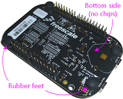
KL25Z pin headers for the expansion boards
For use with the Pinscape expansion boards, the pin headers go on the
bottom side of the KL25Z. The bottom is the side with the
rubber feet, and without any chips. The chips and USB
connectors are all on the top side.
To install the pin headers:
- Fit them onto the solder pads with the shorter pins facing the board
- seat the plastic base flat against the surface of board
- and solder the pins on the opposite side of the board (in this case, since we're installing the pins on the bottom side, the solder goes on the top side)
See 0.1" Pin Headers for more about the pin headers in general.
