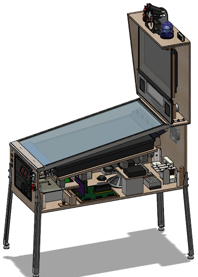
26. Inside the Cabinet
The modern virtual pin cab can be pretty complex on the inside. A
decked-out cab can actually have more equipment packed into it than a
real pinball machine, which is kind of perverse given that this is all
about software simulation. But it makes sense when you consider that
we're not just building a computer; we're building a computer/pinball
hybrid. The computer part by itself has more to it than most desktop
systems, because of the extra monitors and the specialized
input/output peripherals. And the pinball part includes a pretty
large subset of a real machine.
With so much to install, making everything fit can be a challenging 3D
puzzle. I'd like to be able to present a simple, one-size-fits-all
layout here, but that's not really possible. Pin cabs are too
individualized. But I can at least offer one possible solution. In
this section, we'll walk through a model pin cab that includes just
about everything I can think of, and look at where each major element
goes in this setup. The model takes into account the space constraints,
and it also follows my philosophy of serviceability, meaning that it's
designed so that everything can be accessed fairly easily for repairs
and upgrades, even after the machine is fully built.
The arrangement described in this section is based on my own cab, so I
consider many of the design decisions to be tried and true. It's not
an exact replica, though. I've made some revisions in an attempt to
improve things that weren't ideal in my original design. I also made
room for additional equipment that's not in my build. My cab is
pretty decked out, but for the purposes of this section, I've tried to
imagine an "ultimate" cab with all of the toys.
This is, of course, not the only possible solution to the question of
how to arrange things, and I'm sure it's far from the best solution.
Some of it might not work at all for your setup, given that you might
have completely different constraints from your PC packaging or TV
size. So I'll try to explain the rationale behind each element's
placement, so that even if you can't use the exact layout as
presented, you can at least gain some insight from it to use in
formulating your own layout.
Playfield, apron, and flashers
These elements (or some subset of them) form the top layer in the main
cabinet.
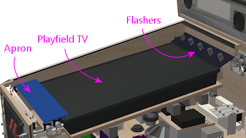
The basic arrangement is pretty straightforward, but the details can
be surprisingly hairy. First, there's the placement of the TV: do you
place it flush with the top of the cab, or recessed like a real
playfield? How far in? At what angle? All the way at the front, or
set back to make room for the plunger? These are all among the most
frequent questions that new cab builders ask. You can see from the
diagram what I prefer, but this is a matter of aesthetics, and there
are other schools of thought. Second, once you've decided upon the
desired look, you still have to implement it physically. That's trickier
than it might look, especially if you want to fulfill my admonition to
make the machine serviceable (Serviceable Design).
Serviceability requires that the TV be easily removed. You can
probably guess I'm not in favor of just nailing it in there and
calling it done.
There's enough to this subject that we've given it its own chapter,
Playfield TV Mounting.
It's extremely important to plan out exactly where the TV goes before
you start arranging anything else inside the cabinet. The TV assembly
forms a ceiling that constrains the vertical space available to
everything else, so you need to know where that is.
If possible, you should actually install the TV early on, not just
make plans, so that you can see the space it delineates for real
rather than just as measurements. But don't do that unless you're
using a mounting that's easily removable, because you won't want the
TV in the way while you're installing everything else. If you use a
mounting system like the one I outline in
Playfield TV Mounting, you'll be able to install and remove
the TV with little effort.
Some notes on the flasher panel. I've depicted the back panel with
the traditional five flasher domes. Each is a clear plastic dome with
a 3W RGB LED inside. This is such a ubiquitous setup that the most
popular pinball software (Visual Pinball with DOF) is programmed to
assume it's there. However, some people replace the five-flasher
panel with an array of individually addressable LEDs - sort of a
coarse dot-matrix display. The physical setup for that is basically
the same; just remove the flasher domes and substitute addressable LED
strips or arrays. Some people also do both, by installing a
five-flasher panel as shown and adding an addressable LED strip or
two, across the top and/or bottom.
See Flashers and Strobes and Addressable Light Strips.
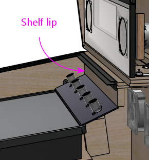
You could also fit one or more light strips across the "lip"
(illustrated below) that sits below the backbox shelf. Keep
in mind that there's a standard trim piece for the top glass that also
affixes here, so check how that will fit before finalizing plans.
See "Rear glass trim" in Cabinet Hardware Installation.
Power inlet
Okay, let's take the TV out and look inside the cab. We'll start with
some simple infrastructure: the power strips. I like to put these at
the very back of the cabinet.
Why at the back? For one thing, that's where the power cord
customarily comes in. For another, it's a really good fit for the
geometry: most power strips are long and narrow, which is a shape that
fits nicely along the bottom of the back wall. And finally, it's good
to put something low-maintenance back there, because that area is
relatively difficult to reach into once everything's assembled. The
very back is blocked from above by the backbox shelf, so it's a little bit
of an inconvenience to access. It's just reachable enough for
plugging and unplugging AC cords, but you wouldn't want to have to get
back there with tools if you can avoid it.
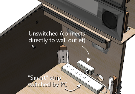
I recommend installing two power strips: a small strip that
you'll plug directly into the wall outlet, and a second, larger strip
that acts as a "smart" strip, providing power to its outlets only when
the PC is powered on. All of the accessories (the TVs, audio
amplifiers, and feedback devices) plug into the switched outlets,
which lets you turn the whole cab on and off with the PC soft power
controls. You can implement the switched outlets by buying a smart
power strip (they don't design them for pin cabs specifically, but
it's the same idea: they're for turning off your monitors and printers
when you're not using the computer), or by building your own. This is
all covered in much more detail in its own section,
Power Switching.
I'd put the large put strip along the base of the back wall, and mount
the smaller strip on the rear wall a little ways above. Put it high
enough up that it won't be in the way of the plugs on the main strip.
We have enough stuff to pack in here that it's important to think
three-dimensionally, so utilize wall space when it makes sense.
The power strips should be secured in place somehow. As always, I'd
avoid anything permanent, such as gluing them down: think
serviceability when choosing installation methods. Adhesive Velcro on
the bottom would be a good choice for the large strip mounted on the
floor. I wouldn't use Velcro for anything mounted on a
vertical surface; the glue on it doesn't hold up over time when under
constant tension from gravity. I'd use some sort of screw-in brackets
instead. Or you could build a little shelf for it (jutting out from
the rear wall), and Velcro it to the strip to the shelf.
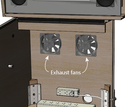
Rear exhaust fans
As long as we're looking at the back, don't forget the exhaust fans.
As mentioned above, the backbox shelf makes this area at the back
cumbersome to access when the cab gets fuller, so it's good to get
the fans in place early.
Rear wall exclusion zone
After installing the power strips and exhaust fans, there's still
a lot of open space on the rear wall. I'd recommend leaving
this space unused for now, for several reasons:
- It's hard to reach after the machine is assembled, as mentioned earlier, due to the way the backbox shelf overhangs this area
- There will eventually be a bunch of wires and cables that you'll have to route through this area from the backbox
- If you're using a liftable playfield TV mounting like the one outlined in Playfield TV Mounting, you'll need to keep most of this space open so that the TV has room to maneuver; plus, the TV overhang will make the space even harder to reach
After everything else is assembled, you can reconsider this space if
there's "just one more thing" you want to install and you can't find
space for it anywhere else. At that point you'll have a more concrete
idea of the constraints on this space, so it'll be easier to decide
if it makes sense to mount anything else here. In my cab, I find this
space so hard to access that I wouldn't put anything here besides
what we've already covered.
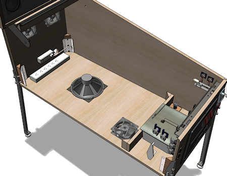
Subwoofer
The subwoofer's position is forced by where you placed the floor
opening for it. That should be installed next, so that you can take
it into account when positioning other things.
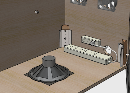
Most subwoofers have screw holes around the perimeter of the speaker
opening. Use suitable wood screws. If you're using a screen cover,
place it between the speaker and the cabinet floor. For a plastic
screen, you might want to pre-cut holes where the screws go; driving a
wood screw through the plastic can bend or twist the plastic.
Intake fans
As with the subwoofer, the intake fan or fans are constrained to be
placed at the openings you made for them, so they should be installed
now to ensure that you don't create space conflicts for them later.
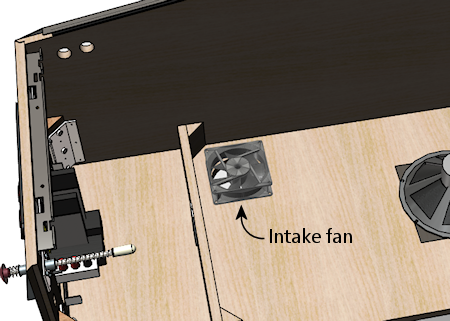
Most PC fans come in square mounting frames (like the one illustrated
above) with screw holes at the corners that you can use to secure the
fan to the cab floor.
Note that you can buy dust filters for PC fans. Since this is an
intake fan, it's a great place to put a filter, to reduce dust buildup
inside the cab. Place the filter between the fan and the cab floor.
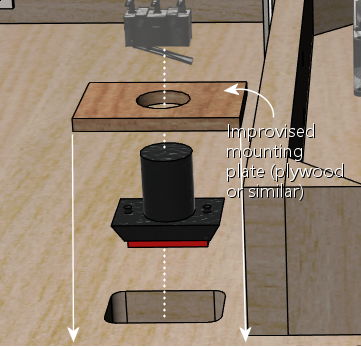
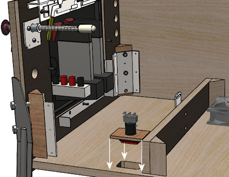
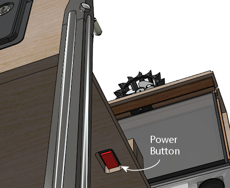
PC power switch
The SuzoHapp "large rectangular button" (part number D54-0004-5x) is a
good form factor for the main power button. It fits in the power
switch opening used in the standard WPC plans, and it's large enough
that it's easy to operate by feel (which is nice because it's hidden
on the bottom of the cabinet, so you want to be able to just reach
under and press it without having to see what you're doing).
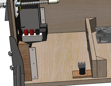
You can install this type of button by creating a small mounting plate
using plywood or any other convenient material. Cut holes in the
mounting plate using the drilling template below, then assemble as
illustrated. Then simply screw the plywood mounting plate into the
cab floor from the inside. This will leave the button perfectly
recessed in the switch opening.
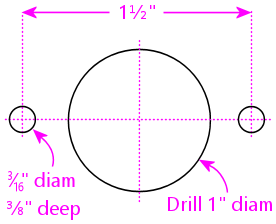
Drilling template for SuzoHapp large rectangular pushbutton
(part D54-0004-5x)
You can easily substitute any of the other similar SuzoHapp
pushbuttons (small round pushbutton, square pushbutton) if you prefer.
I like the large rectangular button because it fits the opening nicely
and it's large enough that it's easy to operate by feel, which is
helpful given the hidden location.
Coin door switch
On a real machine, there's a switch that senses whether the coin door
is open or closed. This is also useful to include on a virtual cab,
because some of the emulated ROMs use it to control access to the
operator menus. See Coin Door for more.
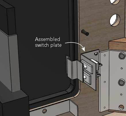
The coin door itself should have a pre-installed metal plate that acts
as an actuator for the switch. This is positioned at the bottom of
the door on the hinge side. It's attached to the door, so that it
swings out when the door opens.
There are different ways to mount a coin door switch (which you can
read more about in the Coin Door chapter), but my
recommendation is to use the standard pinball parts. They're
purpose-built for this, so they're easy to install and reliable, and
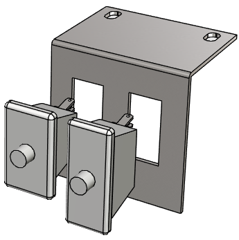
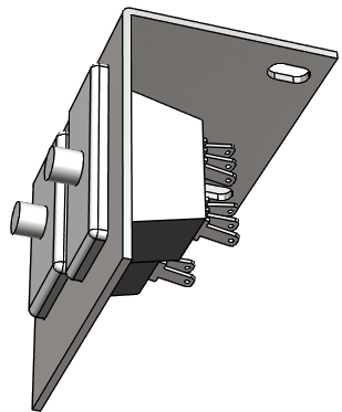
they're not particularly expensive. The standard parts consist of a
metal mounting bracket and a "plunger" switch. The bracket is
designed so that the plunger switch simply snaps - a couple of plastic
clasps on the switch hold in place.
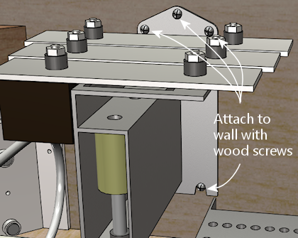
Snap the switch into the plate, then mount the plate so that actuator
on the door presses the switch plunger all the way in when the door
is closed. The plate mounts to the front wall of the cab with
wood screws.
Note that the standard mounting plate has slots for two switches: a
large switch with six connectors, and a small switch with three
connectors. On the real machines, the large switch is used an
interlock to cut off high-voltage power to the playfield when the door
is open, and the small switch is connected to the CPU to let the
software know when the door is open. For a virtual cab, most people
don't bother with the high-voltage interlock, since we don't tend to
have any exposed high voltages to worry about in the first place. So
you probably only need one switch, for the software. The large or
small version will work equally well for that, so just install
whichever one you bought and leave the other slot in the mounting
plate empty.
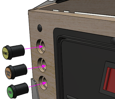
Front buttons
If you're using the common SuzoHapp "small round pushbutton"
assemblies, they're easy to install. Start by disassembling the
button. Gently twist the squarish base about 1/8 of a turn
to free it, then pull it out. Unscrew the nut
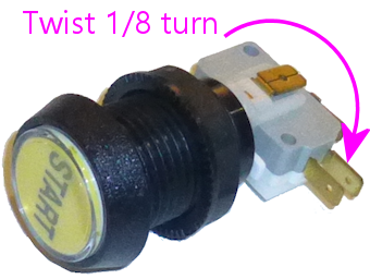
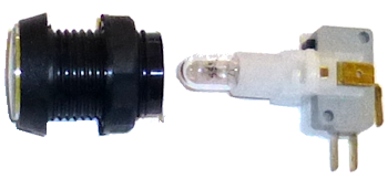
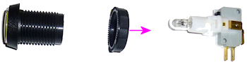
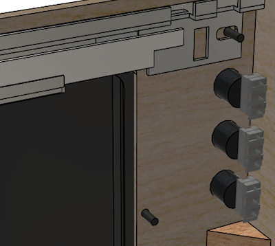
Now just insert the button through the front wall hole (from the
outside) and reverse the disassembly procedure: screw the nut back
onto the shaft, and pop the lamp base assembly back into place, giving
it a slight twist to lock it. The lamp base only fits in a certain
orientation, so just rotate it until you find the magic spot.
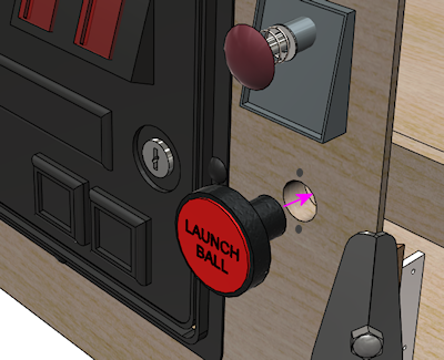
If you're installing a Launch Ball button, it works the same way.
Flipper buttons
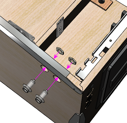
The flipper buttons simply fit through the holes and are fastened with
Palnuts on the inside. The rounded knob on the outside end of the
button tends to be a tight squeeze - I guess that's intentional to
keep them from getting wobbly over time. But it can take a little
effort to force them into the hole the first time you install them.
Seat them by applying pressure from the outside until the collars are
flush with the cabinet wall. (I wouldn't try to force them flush by
overtightening the Palnuts, since I'd be afraid of stripping the
plastic threads.)
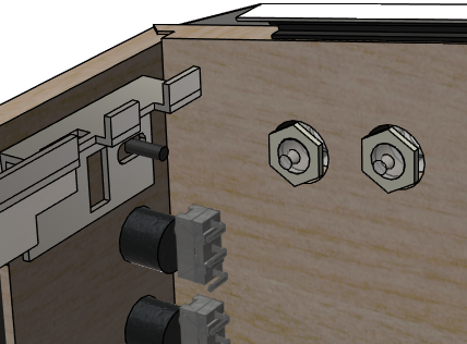
Note that if you drilled the flipper button holes straight through at
1⅛" (which is what I recommend), the Palnuts will be about the
same size as the holes, so they won't clamp the buttons down very
well. Don't worry - this will be fine as long as you're using one or
both of the following:
- VirtuaPin leaf switch holders
- LightMite LED boards
If you're planning to install one of those, you can just leave the
Palnuts loose for now and come back to this later. If you're not
using one of those, and the Palnuts are too loose, you might need to
add a suitable washer.
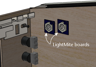
If you're installing the LightMite LED boards, they'll go under the
Palnuts as illustrated below. You'll need to assemble them with
LEDs and connectors first, so hold off on installing them if you
haven't gotten to that yet. See Button Lamps
for more.
If you're installing the VirtuaPin leaf switch holders, they also
install under the Palnut - it should be pretty obvious how those work.
If you're not using the VirtauPin leaf switch holders, you'll need to
mount the leaf switches to the cab wall instead. This takes a tiny
bit of improvisation.
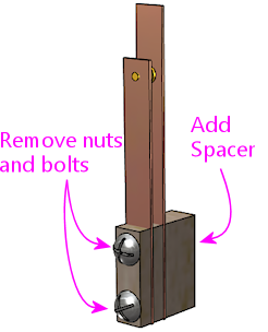
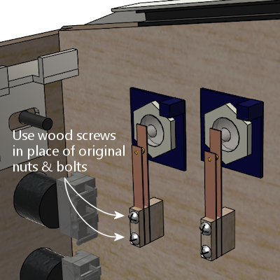
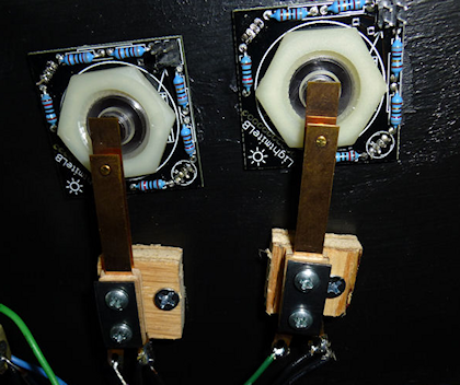
Here's what I did. The standard leaf switches have little insulator plates at
the bottom that separate the switch leaves. The whole thing is held
together by a pair of bolts fastened with nuts. To attach these to
the cab wall, you can take out the nuts and bolts and substitute wood
screws. Use screws long enough to pass through the whole leaf switch
assembly, with about 1/2" left over to screw into the cab wall.
That's almost all there is to it. But there's a slight snag:
the switches will be too close to the cab wall if you mount them
as-is. You need to add a little spacer to move them out from the wall
about a quarter inch. I found that ⅜" plywood was just about
right, so I cut some small (1" x 1") squares and used those as the
spacers.
One last note before you actually install the switches. If you're
installing a plunger, spacing on the plunger side will be tight. The
flipper buttons happen to be positioned right alongside the plunger
rod.
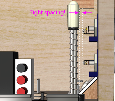
On the real machines, they leave just enough room to make it work, but
we virtual people have an added challenge here, which is that we also
need to install a plunger position sensor of some kind. That can add
bulk around the plunger rod that isn't there on the real machines.
All of the commercial and DIY sensor designers know this is an issue,
and they take it into account in their designs, but space is so tight
to begin with that some of the sensors push the limits here. So you
might find it difficult to make everything fit.
There are two tricks that can help. The first is that you can mount
the switches sideways or diagonally, instead of vertically as shown in
the illustrations above. That can help get them out of the way of the
moving plunger parts. I'd treat this as a last resort, since sideways
mounts can create other conflicts (with the TV or apron, for example).
The second trick only applies if you're using the VirtuaPin switch
holders. If so, then your flipper buttons are extra-long, and you can
swap them with shorter ones. The VirtuaPin switch holders only fit
onto 1-3/8" buttons, whereas most modern commercial pinball machines
use 1-1/8" buttons. So if you're using the longer buttons, you can
save 1/4" by swapping them for the more common 1-1/8" buttons. The
downside is that this requires ditching the VirtuaPin switch holders,
which are convenient, and instead mounting the leaf switches to the
cabinet wall as described above.
Adjusting the leaf switch gap
Most people in the pinball world agree that leaf switches are the only
thing that feel right for flipper buttons, so they're almost
obligatory in a virtual cab. But they do have one downside, which is
that they sometimes need a little mechanical adjustment to get the
switch blades aligned properly. Good operation depends on having just
the right gap size between the contact points.
I wouldn't worry about making adjustments when first installing brand
new leaf switches. I'd start with the assumption that they were
aligned correctly at the factory. However, once you start using the
buttons, keep an eye out for any flaky behavior: missed presses,
random flipper flipping while holding a button down, weird
auto-repeats, etc. If you see anything like that, you can take a
closer look at the switches to see if they need adjustment. You might
even have to re-adjust them from time to time, although in a home-use
cab I wouldn't expect having to do that more than once every couple
of years.
Whatever you do, don't clean the contacts with anything
abrasive. You might see advice in "real pinball" contexts about
sanding or scrubbing leaf switch contacts to remove oxidation. That's
only for real pinball machines with high-voltage leaf switches, which
use tungsten contact points. For a pin cab, it's better to use
switches with gold contact points, since those work better for low
voltages. Abrasive cleaning is bad for the gold contacts since it can
remove the thin gold plating layer. The main reason that you see
people recommend harsh scrubbing for the old tungsten switches is that
tungsten oxidizes over time (especially in the presence of constant
electrical switching), and the oxide layer is a good insulator, so you
have to periodically scrape it off. Gold doesn't oxidize, so
gold-contact switches don't tend to need much cleaning in the first
place. But if you think your switches do need cleaning, use a
slightly damp soft cloth and rub gently.
Testing: If you suspect flaky behavior from your leaf
switches (or any other switches), but you're not sure, you can use
the Pinscape Config Tool to take a closer look. (Assuming you're
using Pinscape as your key encoder - if not, check your key encoder's
instructions to see if it has a similar testing function.)
Fire up the Pinscape Config Tool, and click on the Button Tester
icon on the main screen. This will bring up a window that gives
you a direct view of each button switch at the hardware level.
For the button or buttons that you suspect,
press and hold the button and observe the status shown in the
tester window. If the button is working properly, the on-screen
status should show a nice, steady "On" indication, without any
blinking or flickering. If you see the "On" indication flicker
at all, you should try adjusting the leaf switch as described
below. Likewise, when you release the button, the on-screen
display should show a solid "Off" indication.
Tools: This is one of those jobs where you really need
a special-purpose tool. The right tool makes this otherwise
quite difficult job pretty easy. The right tool in this
case is a "leaf switch wrench", which is essentially a little metal
rod with a slit in one end that fits over a switch leaf and lets you
bend the metal by a precise amount at a precise point. You can buy
these from pinball vendors. On Pinball Life, search for "Ultimate
Leaf Adjuster Tool". I bought one of those a while back
for work on my real pinball machines, and I highly recommend it.
Dennis Miller on vpforums
sent me a great description of how he created his own leaf switch tool
from scratch, so I'll pass that along in case you'd like to
build one yourself as well:
All leaf bending needs to be done with the proper tool. I made mine
out of 1/8" steel rod. I cut a slot 1/2" deep into the end of the rod
with a hacksaw. I then heated and bent the rod at 90 degrees just
above the slot so that the slot was almost parallel to the shaft.
Slide the tool's slot over the leaf at its base insulator stack and
bend very gently, a little at a time, to coax the leaf into position.
The off-angle slot enables working close to cab walls.
How to adjust: Approach this as an iterative process. Make
small adjustments, test, and adjust again as needed. Make your bends
towards the bottom of the leaves, close to the insulators.
- Start with the leaf on the button stem side. Adjust it so that it just touches the button stem when the button is at rest. There shouldn't be any open gap between the button stem and the leaf, so that the leaf starts moving the instant you start pressing the button. But don't overdo it; you don't want the leaf exerting too much extra pressure on the button, as that will make the button feel too stiff. The button already has its own spring for tensioning.
- Once the button side leaf is adjusted properly, adjust the other leaf so that the gap between the contact points is between 1/16" and 1/8".
- A 1/16" gap will make the button engage after pushing it in by about a quarter of its total travel. 1/8" is closer to the halfway point. I think the ideal point is a matter of taste, so test how it feels to see what you prefer.
- Once you've decided on the preferred gap size, you should adjust all of the flipper and MagnaSave buttons to use the same gap, to give them a consistent feel.
Tilt bob
The tilt bob conventionally goes at the front left corner of the cab.
The exact placement isn't critical; just mount it in some free space
below the left flipper buttons. Be sure to leave enough space that
you'll be able to work on the wiring to the front buttons and coin
door.
If you buy your tilt bob as a pre-assembled unit with its own mounting
plate, mounting it is just a matter of screwing the mounting plate to
the cab wall. It's almost as easy if you don't get the assembled
version, though; you just have to mount the pendulum bracket and
the contact ring separately, in the same arrangement as used in
the pre-assembled units. See the illustration below.

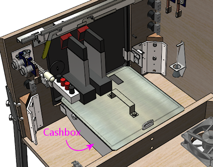
Cashbox
This isn't something you have to "install", exactly; it just drops in.
But the standard type does take up a big chunk of space, so if you're
using that, you might want to keep it in place (or keep it handy)
while you're doing your space planning so that you take its bulky
presence into account.
PC and PSU
We're just about out of the standard "real pinball" parts, so let's
turn to the virtual part of the system. I'd start with the PC, since
it has a fairly large footprint.
Let's look at what we have available, now that we've taken into account
most of the items that have to go at pre-determined locations:
Given this layout-so-far, there's an obvious place where something the
size of an ATX motherboard or enclosed PC case would need to go:
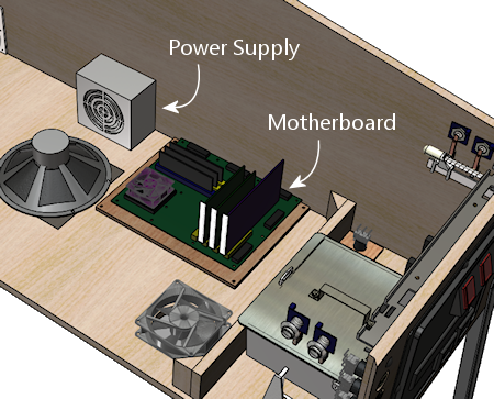
We have a little flexibility with the power supply, but only so much:
it has to be close enough to the motherboard that the power cables for
the motherboard and video card can reach their sockets. The obvious
place is just behind the motherboard. That also happens to take good
advantage of the space there, which is somewhat constrained by the
presence of the subwoofer.
Setting up the PC hardware is a fairly significant project in itself,
so we give that its own chapter, Installing the PC. That section
covers other ways of installing the PC components, such as enclosing
them in a conventional desktop case, and goes into more detail about
choosing a location and implementing the installation.
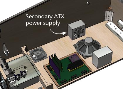
Secondary power supplies
If you're installing feedback devices, you'll need to install power
for them. More details can be found in Power Supplies for Feedback, but
the executive summary is that you can generally cover most of the
bases with ATX power supply (that is, a separate unit of the same type
used for the PC motherboard's power supply) and one or two generic OEM
power supplies for higher voltages (such as 24V and/or 48V).
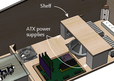
For the secondary ATX PSU, a good location is the mirror image of
where we placed the PC power supply: on the other side of the
subwoofer. Assuming you centered the subwoofer, there's a nice
ATX PSU-sized space on either side, so we might as well use it
that way.
The typical OEM power supplies come in long, low cases that fit well
into the space remaining at the back of the cabinet, between the
subwoofer and the power strips.
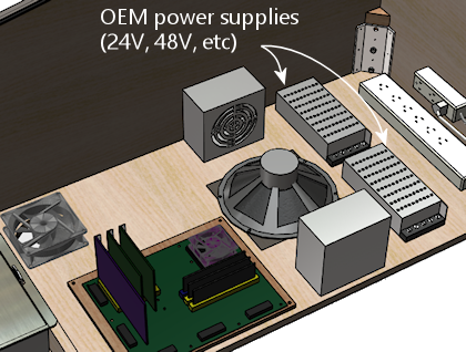
The OEM supplies are usually a good physical fit for this space, and
they're also a good functional fit, in light what I said earlier about
how the back section becomes increasingly inconvenient to work in as
you build out the cabinet. The power supplies are a good
set-it-and-forget-it kind of thing for a hard-to-access space. They
don't have any controls; you just plug them into power.
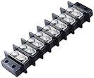
You do have to be able to access their power outputs, though,
whenever you want to plug in a new device. So there's a bit of
advance planning you should do when you install them. Specifically,
you should wire their outputs to connectors located somewhere more
accessible in the cabinet, more towards the front. Many people set up
a group of terminal strips like the one illustrated below somewhere
readily accessible, one for each voltage level, so that they can
easily connect each new device to its appropriate supply when the time
comes. (Be sure to protect any exposed terminals like these with
plastic covers, so that loose wires don't accidentally inject high
voltages into unsuspecting logic boards.)
A nice side benefit of installing the two ATX power supplies across
the aisle from one another is that we can use them to construct a
little shelf across the width of the cabinet. That'll be useful
later: you can see that the floor space is already almost all gone,
and we still have a number of important things left to find room for.
If you've been paying attention, you know how important I think it is
that you be able to access everything in the cabinet even after it's
fully assembled - the principle I call serviceability. So you should
be sure that this shelf can be easily removed! Don't glue it in or
anything like that. At the very least, fasten it with a couple of
easily removable screws. But better yet, use something you can undo
without tools: attach it to the power supplies with Velcro, for
example, or use toggle latches to lock it down. That way it'll only
take a few seconds to remove it if you have to get to the power
supplies.
Chime unit
See Chimes and Bells. This is a little percussion instrument that
replicates the iconic bings and bongs of the electro-mechanical
pinballs from the 1960s and 70s. The best way I know to accurately
reproduce the original sound is to find an authentic used chime unit
from an old machine, as they have some engineering that's hard to
replicate in a DIY design. The real units are quite bulky, though,
which limits where we can put them. The only place where a chime unit
will fit in our hypothetical fully-loaded cab is in a corner at the
back.
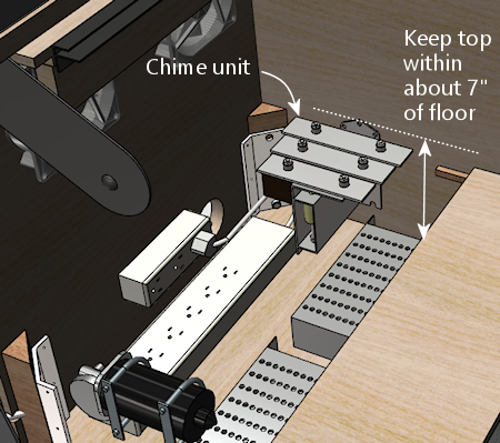
The original chime units are designed to be mounted to a side wall.
Use wood screws to attach it via the integrated mounting plate.
Try to keep the top within about 7" of the floor. This will help
avoid any clearance issues with the back of the TV when you lift it
up. (Assuming you opt for a liftable TV mounting, as outlined in
Playfield TV Mounting.)
Much as I don't like hiding things away in the back of the machine, we
really don't have much choice when it comes to the chime unit.
There's just not enough space anywhere else. If your cab won't be as
fully loaded as the one we're developing here, though, you might have
some space for it in a more convenient area, so by all means put it
somewhere better if possible. I don't think the placement makes any
significant difference acoustically. For what it's worth, most of the
original machines that used these units also placed them in a corner -
typically the right front corner, below the plunger.
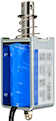
Shaker
See Shaker motors. The shaker is another bulky toy, and in this
case it must be mounted on the cabinet floor to get the proper
effect. Fortunately, we have one large floor section still remaining,
mid-cab, opposite the PC motherboard.
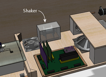
Happily, this works out well, as this is just about exactly where we'd
put the shaker anyway, to get the best tactile effect, if space were
no concern. You want the shaker to be mounted with its motor axis
parallel to the cabinet's long axis, and that's a perfect fit for the
available space. You also want the shaker to be in roughly the middle
of the cab front-to-back so that it imparts a balanced sideways
motion. There's no benefit in centering it side-to-side, so I'd mount
near the wall, to leave more room around the PC for cable connections.
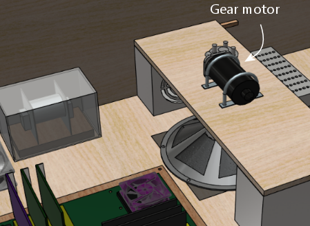
Gear motor
See Gear motors. These are meant to reproduce the sound of
the motorized playfield features on many pinballs from the 1980s and
1990s, such as Thing from The Addams Family or the castle gate
from Medieval Madness. To localize the sound effect properly,
the gear motor should be somewhere towards the back of the cabinet,
since the playfield features it's meant to imitate are typically
towards the back of the playfield. (The playfield features in
question are all unique to each game, so they're all in their own
unique locations, but for the most part they're somewhere near the
center rear of the playfield.)
There are two rather different types of motors that pin cab builders
tend to use for these. One type is the small robotics servomotors you
can buy on eBay. Those are so compact that space planning really
isn't an issue for them. The other popular type is an automotive
windshield wiper motor. Those are quite a lot larger, and do require
that you block out some space for them. We'll proceed with the
assumption that you're working with the larger type and need to find a
place for it.
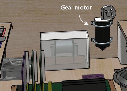
If you're using a liftable TV frame design, you might be able to mount
the gear motor on the bottom side of the TV frame. That would let you
put it right in the middle of the playfield area, which is the ideal
location for the sound effect, plus it's easy to access for service.
This is the right option if you have a compatible TV mounting.
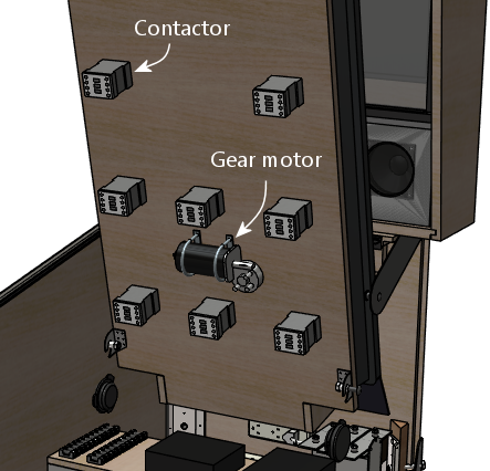
In the illustration above, we're assuming that the contactors for the
bumpers and slingshots are also mounted under the TV. A gear motor
should fit nicely between the "bumper" rows in the back half of the
playfield. See "Mounting contactors under the TV"
below for more about this.
If an under-the-TV mounting doesn't work in your cab, there are
several places it might fit. One possibility is to place it alongside
the shaker:
A second option is to use the little shelf we built over the ATX
power supply and subwoofer area:
The shelf is probably the best location in terms of localizing the
audio effect, and it's a great location in terms of service access.
The only problem is that there are a couple of other devices we'll
come to later that we'll need the space for. So we're not
going to be able to leave it here in the model we're developing, but
you can keep this location in mind as an option in your cab, if the
space ends up being available after you consider where the rest of the
parts go.
A third option is to place it in a corner at the back:
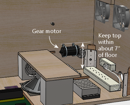
If you go this route, try to keep the top within about 7" of the
floor. This will help avoid any clearance issues with the back of the
TV when you lift it up. (Assuming you opt for a liftable TV mounting,
as outlined in Playfield TV Mounting.)
As I've said a few times, this isn't a great area to mount just about
anything, because it's hard to reach into in an assembled cab. But
gear motors tend to be zero-maintenance, so if you have to put
something back here, a gear motor isn't the worst choice. What I'd
recommend is to use a mounting apparatus that you can remove without
tools if necessary. Something like this, perhaps:
- Mount the motor to a small sheet of plywood (cut just large enough for the job) with a pair of "U" clamps, which you can buy at any hardware store
- Use something like a Z-clip (a heavy-duty type of picture hanger) to hang the plywood carrier on the wall
- Secure the bottom with a thumb screw or toggle latch, so that it can't come loose from the hanger
If you do need to access the gear motor, this will let you take it out
as a unit without having to do anything too complicated in the
confined space. Once it's out, you can make whatever changes are
needed, and just as easily put the whole unit back in place.
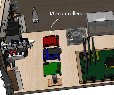
Controllers
See I/O Controllers. A pin cab requires some special USB
devices to connect the button inputs, plunger sensor, and feedback
devices. There are several options for these, but whichever you
choose, you're going to have some little circuit boards that you'll
need to mount somewhere in the cab. Most cabs need two or three
boards, most of which are on the order of 4" by 4".
Most of these boards can go just about anywhere that's convenient, but
there's one type of board that's pretty particular about location: the
accelerometer, also known as the nudge sensor. That board should be
mounted horizontally, close to the front of the cab, preferably close
to the center of the cab. The accelerometer senses the cabinet's
motion, and it does the best job at that if it's mounted in a central
location near the front.
If you're not using a full-sized cashbox, then you still have a
nice open space at the front, where the cashbox would go on a real
machine. That's an ideal spot for the controllers.
If you are using a full-sized cashbox, we're in a bit of a jam
now, because there's enough floor space left for the controllers.
This is, in fact, why I don't have a real cashbox in my own cab. But
I don't really like my hokey improvised substitute (a plastic food
container that happens to be about the right height, with holes cut in
the lid to line up with the coin slots). So given that this section
is about an idealized ultimate cab with everything, let's see how we
could make this work.
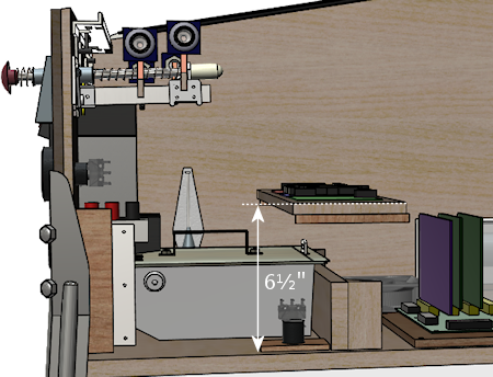
My proposal is basically to create some new floor space, by
thinking three-dimensionally:
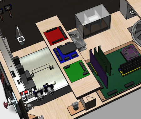
What you're looking at is a shelf, running the width of the cabinet,
about 6½" above the floor, positioned over the back portion
of the cashbox.
This reclaims the floor space that we gave up to the cashbox. It's at
the right position for our accelerometer, and it gives us enough space
to mount a typical complement of I/O controller boards.
Some important considerations:
- For the sake of the accelerometer, the shelf must be quite solid, and quite solidly mounted to the cabinet. It must move with the cabinet; it shouldn't impart any extra vibration or wobble of its own. For this reason, I think this shelf needs to be securely screwed in, not held down with Velcro or anything like that. But I think it's okay for this shelf to be more or less permanent, since, if it's properly positioned, it won't block access to anything.
- Position the shelf so that it doesn't block access to the motherboard. This is especially important given that it needs to be so solidly (permanently) attached to the cabinet.
- Use a sturdy material. I'd recommend a good quality 3/4" hardwood plywood, the same sort of material used for the cabinet itself. The shelf doesn't have to support any significant amount of weight, but remember that we want it to be very solid so that we get good accelerometer readings.
- At the recommended height, the shelf will leave enough space that you can still conveniently maneuver the cashbox in and out through the coin door, as intended.
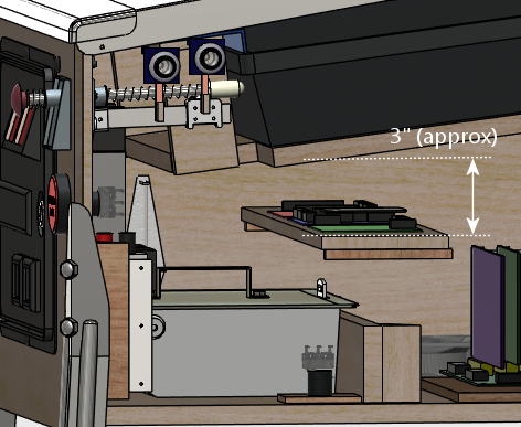
- At this height, the shelf should also leave comfortable clearance for a typical playfield TV with my recommended mounting. For the purposes of the model, I assumed what are probably the worst-case conditions in terms of how much headroom we have here: a fairly thick TV (3.5") and a "deep" mounting style (with the TV at full playfield depth). With those assumptions, we still have about 3" of headroom to work with here. That's plenty of space for any of the controllers I've encountered.
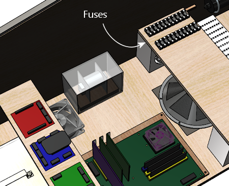
Fuses
See Fuses. Fuses can be used to protect your output
controller from overloads. You don't necessarily have to include a
fuse for every device, but it's good to cover the higher power
devices, such as motors and solenoids.
Your output controller might have its own built-in fuse holders, but
most of them don't, so fuses usually have to be installed separately.
We're going to assume you're installing them separately.
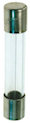
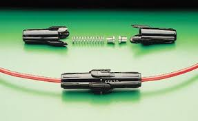
There are many types of fuses and fuse holders. For my own cab, I
went with the type that's common on the real pinball machines (not for
the sake of realism, but just because it saved me the trouble of
researching all of the other options). Those are the so-called 3AG
glass cartridge fuses, which look like this:
These can be used with little plastic holders that look like this:
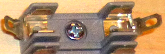
This type of holder is designed to be mounted to any sort of surface
with a screw (which you can see in the photo), so we can mount these
on any convenient wood surface on the cab, such as the floor, a wall,
or that center shelf we created earlier over the ATX power supplies
and subwoofer:
I like the idea of centralizing the fuses in one big set like this,
since it makes it easier to find the fuse for a given circuit.
However, it has some disadvantages: it takes up a big block of space,
and it requires extra runs of wire to and from the central fuse panel.
You also have to make a chart of what each fuse is connected to.
Another option that you might prefer is to place each fuse near the
device it's connected to. The individual fuse holders are small and
can mount just about anywhere, so ad hoc placement per fuse avoids the
need to allocate space for a central fuse panel. And it can save a
lot of wire, since you can place each fuse somewhere along the section
of wire that you'd have to run out to the device anyway. Finally, it
might be easier to figure out which fuse goes with which device this
way, as long as you can manage to place each fuse physically close to
its device.
Keep in mind that the type of fuse holder pictured above has two
exposed metal terminals. If you're creating a central fuse panel out
of these, you should consider placing a plastic cover over it to
protect it from accidental contact from tools or loose wires. If
you're scattering the fuses (rather than creating a central panel),
you might want to use a more fully enclosed fuse holder instead of the
open type. For example, take a look at the Littlefuse 155 series
in-line twist-lock holders. Those are designed so that there are no
exposed terminals.
Littlefuse 155 series in-line 3AG fuse holders
Contactors (and other solenoid simulators)
See Flippers, Bumpers, and Slingshots. The real pinball machines have a lot of
powerful solenoids that kick the ball around and actuate other
playfield mechanisms. They're are strong enough that you can not only
hear them but feel the kick. Virtual pinball software can manage the
audio part with recorded audio, although that tends to be a weak
imitation that you'd never mistake for the real thing. In a pin cab,
we can do better, by simulating the kick of the solenoids with actual
solenoids. That can get a lot closer to the real sound, and can also
reproduce the tactile effect.
There are several types of solenoid-based devices that pin cab users
employ as substitutes for pinball solenoids: contactors (such as the
Siemens type pictured below), automotive starter relays, generic
open-frame solenoids, and even real pinball solenoids and their
associated mechanisms.
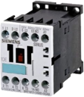
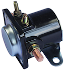
Common devices used to simulate pinball coil effects: Siemens
contactors; Ford starter relays; generic open-frame solenoids.
For the purposes of our illustrations, we'll use the Seimens
contactors. The Ford starter relays and most open-frame relays should
comfortably fit the same spaces, so you should be able to substitute
them without making other changes.
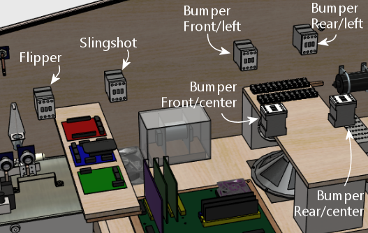
The standard complement of contactors consists of 10 units:
- Two flippers (left and right)
- Two slingshots (left and right)
- Six bumpers (three across the middle, three across the back)
The goal is to locate each contactor so that it matches up with the
position of the device it's intended to simulate, as it'll appear on
the main TV screen when you're playing a game. So you want the
contactor that's going to serve as the "left flipper" to line up
roughly with where the simulated left flipper is drawn on the TV
screen. It's obviously impossible to get that perfect for every game
when you're going to have hundreds of simulated games to choose from.
But all pinball playfields tend to follow the same template for the
core elements around the flipper area, and anyway, we don't have
to get it perfect, just close enough to be convincing.
So, taking the desired positions into mind, here's how we can
arrange the ten devices to fit the available space. Note that
the devices illustrated on the left wall are mirrored on the
right wall, but we're leaving them out of the diagram for the
sake of readability.
Mounting contactors under the TV
If you're using a liftable TV mounting like the one described in
Playfield TV Mounting, you can move most of these to the
bottom side of the TV mounting frame, as illustrated below.
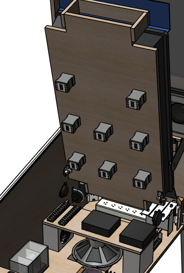
Here we've moved all of the contactors except the flippers to the
underside of the TV frame. We left the flippers where they were (on
the side walls), because the natural place for them on the TV frame is
a bit too close to the shelf where the I/O controllers are located.
If we didn't have that shelf, we could easily move the flipper
contactors to the TV frame as well. This is what it looks like
when we lower the TV back into its normal position:
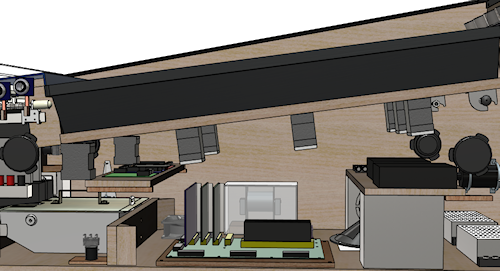
As you can see, there's lots of room for everything, except for
the area around the I/O controller shelf.
The under-TV mounting style has some distinct advantages:
- It places the devices closer to the on-screen elements they're intended to simulate
- It frees up space along the cabinet walls
- There's more room for larger devices than the original side-wall mounting
- The contactors are easier to access for service, since they're more out in the open after you lift the TV up
I don't think there are any real disadvantages, either. I think it's
the right way to go if you have a suitable TV mounting. And it's
practically required if you plan to use real pinball mechanisms for
any of the solenoid devices; they're too large to be workable with the
side-wall mounting.
There is one important consideration if you go this route. You'll
definitely need to use a pluggable connector for the wiring to the
contactors, so that you can remove the whole TV-and-frame assembly
from the cab without having to cut wires. I recommend using one
of the Molex .062" wire-to-wire connectors, which are available
in plugs with up to 12 pins. That lets bundle the wiring for the
whole set of contactors into a single plug.
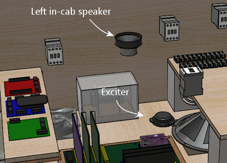
In-cab speakers
See Audio Systems. We've already covered the subwoofer, which
traditionally goes on the floor in the middle of the cab. But many
cabs also include a set of mid-range speakers inside the main body.
These are usually in addition to the speakers in the backbox,
and serve a different purpose. The backbox speakers are there to play
the ROM music and voice effects. The speakers in the cab are there to
reproduce mechanical sounds that aren't already covered by the
solenoids and contactors. For example, the sound of the ball rolling
and bumping into things.
Visual Pinball has the ability to separate the music from the
mechanical effects and play each type of through a separate set of
speakers. Playing back the mechanical effects through speakers inside
the cabinet makes them seem to come from the playfield, improving the
illusion. VP 10 takes this one step further, by supporting a
four-speaker "surround sound" arrangement that localizes each sound
effect to the right point in the playfield plane.
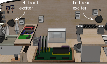
There are several ways to configure in-cabinet speakers. If I were
building a new cab today, the only option I'd consider would be a
four-exciter system. This takes advantage of VP 10's spatial
localization capability to position effects in different parts of the
playfield.
An "exciter", by the way, is a type of speaker that works by making
the surface it's attached to vibrate. A conventional speaker works by
vibrating a paper cone. An exciter uses whatever it's attached to in
place of the paper cone. They're better than conventional speakers
for an in-cab speaker system for several reasons:
- They're much smaller than regular speakers, so it's easier to find room for them in a crowded cab
- They're made specifically to be mounted to flat surfaces (like the wall of a pin cab!)
- They work by transmitting their sound energy through whatever they're attached to, which better reproduces the way mechanical sounds in a real pinball machine travel through the cabinet
- Transmitting the sound through the cab wall produces more of a tactile effect than a regular speaker does
The ideal mounting positions are at roughly the corners of the TV.
That's the arrangement that the VP software assumes when it calculates
the volume mixing levels to create the illusion that the sound is
coming from a particular point in space. It's pretty simple to
install exciters this way: just install two on each side wall,
below the TV, one near the front and one near the back. Most
exciters are quite flat and compact, so it's not hard to find
room even with everything we've installed so far.
Some people add one or two subwoofers to this setup as well. I
personally don't think that's necessary. For the types of sound
effects we're talking about in a pin cab, the only reason you'd want a
subwoofer is for more of a tactile effect. Exciters are already good
at producing tactile effects because of the way they transmit the
sound energy through the cab wall, so I think a subwoofer is
redundant. Besides, if you really need more bass from these channels,
you can make Windows mix the low-frequency bands from the surround
channels into the main subwoofer output.
I built my own cab before VP supported the four-channel surround
system, so I took a simpler approach, with two regular speakers and
tactile subwoofer:
This produces a decent effect, certainly better than no in-cab
speakers at all, but the lack of spatial positioning is sometimes too
obvious. It's particularly noticeable when the ball is near the top
or bottom of the playfield, since the sound always comes from a fixed
spot in the middle. That's why I'd go with the four-speaker system
now that it's an option.
Amplifiers
See Audio Systems. Unless you're using powered speakers, you'll
need some amplifiers. Most pin cab builders use small car amps, since
they're compact and (like everything automotive) run on 12VDC power.
Most of the cheap units can power a stereo speaker pair or a stereo
pair plus subwoofer (the latter being known as a 2.1-channel amp).
Many higher-end car amps can power four independent channels.
You'll typically need the following:
- One 2.1 amp for the backbox speakers + main subwoofer
- A second 2-channel or 2.1 amp for the front surround speakers
- A third 2-channel or 2.1 amp for the rear surround speakers
I've been keeping space for a couple of these units open on the
shelf over the subwoofer area:
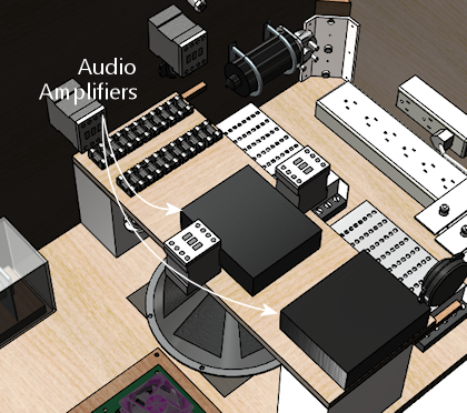
What you can fit here will obviously depend on the specific equipment
you choose. You can probably fit two small car amps, and maybe three,
if you're able to stack two of them vertically.
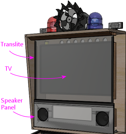
Backbox
In the backbox, as in the main cabinet, we have a top layer that's
visible to the player. In the backbox this consists of the translite,
backglass TV, and speaker/DMD panel.
Those are all covered in detail in other sections:
- "Creating a translite" in Backbox Hardware Installation
- Selecting a Backbox TV (designing the backbox layout and choosing a backbox TV)
- Backbox TV Mounting (installing the TV)
- Speaker/DMD Panel (fabricating and assembling the speaker/DMD panel)
There are some additional items that we can fit into the backbox, mounted
on the back wall.
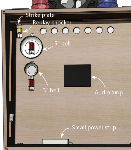
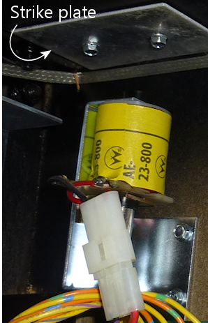
- Replay knocker: typically mounted at the top of the backbox in a corner. The knocker coil is mounted so that the open end points up at the ceiling, with about a 1" gap to the ceiling. The metal strike plate is mounted on the ceiling right above it. See Replay Knockers.
- Shell bells. If you're a big fan of machines from the electro-mechanical era, you can install a couple of round bells with solenoid hammers. Similar bells were used in many machines from the 1960s and 70s. These serve exactly the same function as chimes, so in a way they're redundant with a chime unit, but the reason you might want to have both is that bells and chimes each have their own distinctive sound. Some games from the EM era had bells and others had chimes, so you can more accurately re-create a greater variety of games if you have both. The backbox is a good place to install bells if you have them; the bells have a large footprint, but they're flat enough to fit behind a TV (in most cases, anyway), so this takes good advantage of the wide but shallow space in the backbox. As a nice bonus, it's true to the originals: it's where bells were usually situated in the EM machines. See Chimes and Bells.
- Repeating bell (not shown). The shell bells above work like chimes in that they fire with one hammer strike at a time. There's a different kind of bell used on some machines from the 1980s, which rings continuously when energized, like an old-fashioned alarm clock or telephone ringer. These look just like the shell bells, so they're an equally good fit for this space. There should be plenty of room to add one of these if desired. See Chimes and Bells.
- Audio amplifier. We already proposed a place where you can fit a couple of car-radio amplifiers into the main cabinet. You might also be able to fit an amplifier into the backbox, either as an alternative to the main-cabinet mounting or in addition (which might be necessary if you need four channels of audio in the main cab for a surround-sound setup). You'll probably have about 1" to 2" of depth to work with behind the TV, which is enough to fit a small amplifier.
- Power strip. There should be enough space on the floor of the backbox behind the DMD panel to install a small power strip. A 3-outlet strip fit easily in my backbox in this area. It's convenient to have a few outlets here, so that you can plug in the backbox items (TV, DMD panel, audio amp) without having to run more cables through to the main cabinet.
