47. Feedback Device Wiring
The basic principle of operation for all feedback device wiring is
that the output controller acts as a switch for the device's power
connection.
Before we get into that, though, let's start small, by just thinking
about how you'd set up the power wiring for a device on its
own, without having any sort of output controller or switching
involved. This would be a simple matter of hooking up wires between
the (+) and (-) terminals on the power supply and the device:
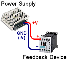
Wiring a feedback device directly to a power supply.
A device wired this way will simply stay on all the time, and
there will be no way for the software to control it.
Now, that's obviously useless for a pin cab, since it just makes the
device turn on and stay on. The one exception is that you might wire
some of the lamps in your front-panel buttons this way, if you don't
care to place them under software control. And now that you mention
it, this is exactly how the lights in my coin chute "reject" buttons
are wired. There's really no need for them to ever turn off. Even on
a real pinball machine, those are just hard-wired to power all the
time. But for just about everything else, you'll want the software to
control the device state, so this simple circuit plan simply won't do.
But you already knew that - the whole point of this section is
output controller wiring, after all!
So how exactly do we insert an output controller into this picture?
The exact details can vary a little bit depending on the type of
controller you're using - and we'll show you those exact details for
each type of controller in the chapters ahead - but the principle is
always the same. The basic idea is that we "cut" one of the power
wires, and stick the output controller into that gap.
Basic plan for solid-state controllers
We're going to start with the "solid-state" controllers - LedWiz,
PacLed, and Pinscape. We call these solid-state controllers because
they use transistor switches to turn the attached devices on and off.
We start with these because they all work roughly the same way,
and they all have a fairly simple approach to connecting devices.
The alternative to a solid-state controller is a relay-based
controller, such as a SainSmart board. And even for those, most of
what we're going to cover for the solid-state controllers applies,
which is another reason we're starting with those. We'll cover the
specifics of the relay boards later on, but I hope you'll read through
the solid state section first to get a mental picture of how all of
this works in general terms. Just be aware as you read the
solid-state material that there will be a few little differences for
the relay boards. We'll provide the exact circuit
diagrams for the relay boards in SainSmart Relay Board Setup, so treat the circuit
diagrams in the solid-state section as "theory" rather than practice.
The same goes if you're using a relay board to "boost" an LedWiz or
PacLed's power. I sincerely hope you're not thinking of using a
relay board to boost Pinscape's power, though, because the expansion
boards are such a better way to do that.
If you're using a solid-state controller - Pinscape, LedWiz, or PacLed
- you'll be able to follow the wiring diagrams in this section pretty
literally, so you can pay as much attention to the details as you
like. The same applies if you're using any of these boards with a
solid-state booster board, such as one of Zeb's booster boards or a
Pinscape DIY booster circuit.
Okay, let's get back to this idea that we're going to "cut" into
one of the power wires to interpose the output controller as a
"switch" that can turn the device on and off by controlling its
power connection.
For all of the "solid-state" output controllers (Pinscape, LedWiz,
PacLed), you don't have any choice about which wire has to be
cut. The cut always goes in the (-) wire for these
controllers:
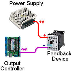
Basic feedback wiring plan for LedWiz, PacLed,
and Pinscape. Connect the feedback device's (+) terminal
directly to the power supply (+) terminal.
As you can see, we did as described above: we "cut" the wire between
the feedback device's negative (-) terminal and the (-) terminal on
the power supply, and we inserted the output controller into the gap.
Specifically, we connected the device's (-) terminal to a "port"
on the output controller.
If you're paying close attention, you might want to point out a big
error in this diagram: we lost a piece of wire here! The connection
that we had before to the (-) terminal on the power supply is nowhere
to be seen! You're right - that connection is definitely required.
The reason we didn't show it is that it's actually part of the output
controller's basic wiring that you set up when you install the output
controller itself. It's not something you have to add for each
device. For the sake of completeness, though, let's put it back
into the picture:
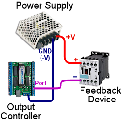
A more complete view of the basic feedback
wiring plan, showing the output controller's wire back to the (-)
terminal on the power supply. This was elided in the earlier
diagram because it's part of the basic wiring that you do when
you set up the output controller, not something you have to add
for each device you connect.
To clarify what we mean about not having to add this wire for every
device, let's look at how you'd add a second device to this
setup. To add a second device, you'd just add the two wires
we showed in the first picture: the wire from the power supply
(+) to the device (+), and the wire from the device (-) to the
output controller port. For a second device, you'd of course
use a different port, since each device must have its own
separate port.
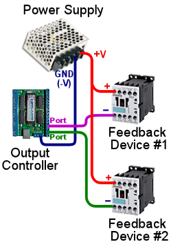
Adding a second device to the controller.
The new device is wired just like the first device, using a
separate port on the controller. Note that we don't have to
add another wire back to the power supply (-) port: all devices
share a single "ground" connection.
There are two things to notice here. The first is that, as we pointed
out, you don't have to add another connection to the power supply's
(-) terminal. The single "ground" connection that you set up when you
install the controller is shared by all devices, so adding a new
device only requires the two wires: power supply (+) to device (+),
and device (-) to output controller port. The second thing to notice
is that we "daisy-chained" the power supply connections. We didn't
have to run a separate wire all the way from the second device back to
the power supply; it's sufficient to connect them through the same
wire. This can save you a lot of wire, since you'll probably have a
few devices that are fairly far away from the power supply.
This is all well and good if you want to hook up a bunch of devices
that run on the same voltage. But what about devices that run on
different power supplies that use other voltages? If you already read
through Power Supplies for Feedback, you know that you might need
as many as five or six different voltages if you're using a diverse
mix of devices:
- 5V for flasher LEDs
- 6.3V for incandescent button lamps
- 12V for the shaker motor and gear motor
- 14V for #161 lamps in the big square buttons
- 24V for contactors and chimes
- 30V or more for the the replay knocker
So how do you hook up all of these different devices, when each one
has to be connected to its own power supply? What happens to that
common wire back to the (-) on the power supply when we have five
power supplies?
Happily, this turns out to be easy. If you go back and review the
section on Interconnecting
Grounds in the Power Supplies chapter, you'll find the answer.
You're going to explicitly wire all of your power supply (-) terminals
together when you set up the power supplies.
So that wire that connects from the controller to the (-) terminal on the
one power supply actually connects to the (-) terminal on all
of the power supplies. This important power supply setup step is
explained in detail in Power Supplies for Feedback.
Now that we've settled the question of the (-) wire, it becomes
straightforward to connect a mix of devices that use different
power supplies. You just repeat that same formula for each device
and its particular power supply: device (+) to power supply (+),
device (-) to output controller port.
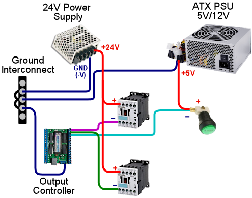
Adding a third device that uses a different
voltage and a different power supply. The new device is wired
just like the other devices, with its (+) connected to its power
supply (+) and its (-) connected to an available output port.
All power supply (-) terminals are connected together at a common
ground interconnect point, so the output controller's GND connection
only has to connect to the common interconnect point.
Hopefully, it's clear now how this generalizes if you wanted to add a
third or fourth power supply to the mix. I don't want to elaborate
the diagram any further to show even more devices and power supplies,
since it's already getting pretty busy (and I'm running out of colors
for the wires), but you just apply the same principle for each
additional power supply:
- Connect the power supply (-) to the common ground interconnect point
- For each device using the power supply's voltage, connect the device's (+) terminal to the power supply (+) terminal, and connect the device's (-) terminal to a free output port
Basic wiring plan for relay-based devices (SainSmart)
If you're using a SainSmart USB relay board, or some other type
of relays, the wiring plan is almost the same as shown above.
There are two slight differences, though.
First, with a relay, you can "cut" either the (+) or (-) supply
wire to insert the relay into the circuit, but it's considered better
engineering practice to insert the relay into the "+" wire. That's
the way it's shown in the diagrams in the SainSmart Relay Board Setup, which
is part of why I warned you earlier that the relay-based wiring
diagrams would look a little different when you got to them. (The
reason it's better to cut the (+) wire is that this leaves the device
without any live positive voltage connected when it's switched off.
That's safer in case you accidentally touch one of the wires, or
there's an accidental short circuit.)
Second, relay boards don't have that single common ground wire
that runs back to the shared (-) terminal interconnects. Instead,
you simply insert the relay into the circuit as though it were an
ordinary switch (which, in fact, it is!).
See SainSmart Relay Board Setup for more details on the SainSmart boards
in particular.
Device-specific wiring considerations
You can use the basic wiring plan above with all types of feedback
devices. However, some devices have additional, special wiring needs
of their own that you have to add onto the basic generic plan.
The sections on the individual device types contain details on
any special wiring requirements, but here's a quick overview of
the things you have to watch out for.
LED current-limiting resistors
LEDs always require something to limit the amount of current
(amperage) going through them. Without some kind of current limiter,
an LED acts like a short circuit, which will make it overload itself
or its power supply. The simplest and most common type of current
limiter is a resistor placed in series with the LED.
For a detailed explanation of LED resistors, including a calculator
to pick resistor sizes, please see LED Resistors.
Diodes for coils, motors, solenoids
Any feedback device that uses a magnetic "coil" requires that you
install a protective diode on the device. All coils inherently cause
voltage spikes that can damage other components in your cab and can
cause weird computer glitches. Diodes are used to suppress these
spikes. They're cheap and install to install, so don't omit them.
The following all require diodes:
- Motors (shakers, gear motors, fans)
- Solenoids
- Contactors
- Replay knockers
- Chime coils
- Other pinball coils
- Relays
For details on what types of diodes to use and how to install them,
see Coil Diodes.
AC devices
It's rare for anyone to use an AC-powered device in a pin cab, but I
wanted to mention this just in case: Do not connect an AC-powered
device to any of the solid-state output controllers. All of these
(LedWiz, PacLed, Pinscape) are designed to work with DC voltages only.
I recommend avoiding this issue entirely by sticking with the common
DC-powered devices, but if there's something AC-powered that you
really want to include in your cab, it's possible with a little extra
work. What you have to do is connect an AC-compatible switching
device between the output controller and the AC device.
You have a few options for the switching device:
- Relay
- Solid-state relay
- H-bridge
If you're using a SainSmart USB relay board as your output controller,
you already have this covered, because those use AC-compatible relays.
You can connect an AC-powered device to the SainSmart the same way
you'd connect any DC-powered device.
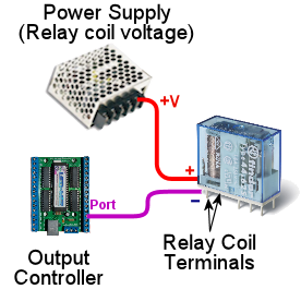
If you're using one of the solid-state controllers, I'd recommend
keeping it simple by using a relay. Here's how. First, connect the
relay coil to a port on your output controller exactly as though the
relay coil were an output device in its own right:
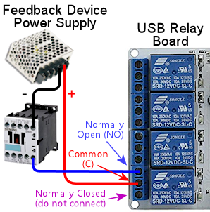
Now connect the AC device to the "Normally Open" (NO) and "Common" (C
or CMN) contacts on the relay. Run the following wires:
- From one AC power supply terminal to the relay NO terminal
- From the relay CMN contact to one power terminal on the device
- From the other power supply terminal to the other device power terminal
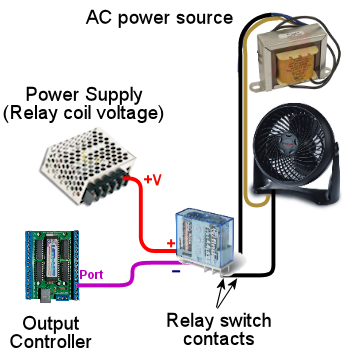
If you're familiar with solid-state relays or H-bridges, you can use
one of those devices in place of a relay. Those generally aren't
designed to be directly compatible with LedWiz or Pinscape-style
switching, though, so you'll likely have to rig some additional
circuitry to make that work. I'm going to leave that as an exercise
to the reader for those are so motivated, and recommend that everyone
else go with the simple relay setup described above.
