95. Expansion Board Power Cables
Each of the expansion boards has two connectors that have to be
plugged into ATX power supplies. These are designed to work with
special, custom power cables that you build as part of the expansion
boards. This section explains what's needed and how to build the
cables.
Connection plan
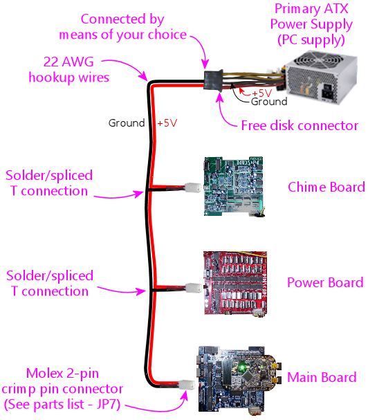
There are two cables, one for the "primary" ATX power supply, which is
the one that powers your pin cab's PC motherboard, and one for the
"secondary" ATX supply, which is dedicated to powering feedback
devices.
The "primary" cable connects to your PC's power supply at one end,
and then runs in a daisy-chain to each expansion board, plugging
into the "PC PSU" connector on each board.
Here are some things to note:
- This is a custom power cable that you're going to construct out of hookup wire and the Molex 2-pin crimp-pin connectors in the parts list
- The connection at the ATX power supply end can be handled in a few different ways, such as using a compatible plug to plug into a free disk connector, using a breakout board, or soldering directly to a disk cable on the power supply; we'll look at the details later in this section
- The primary power connector only needs two wires: the red +5V wire, and the black Ground wire; these connect to the corresponding wires in the ATX disk connector or breakout board
- Each expansion board has its own plug
- The plug for each board is the same type
- Each plug connects back to the main wire with a "T" connection
- You can solder the connection at each "T"
- Or you can a "T-Tap" splice connector for a solderless joint (available at Amazon, Home Depot, etc)
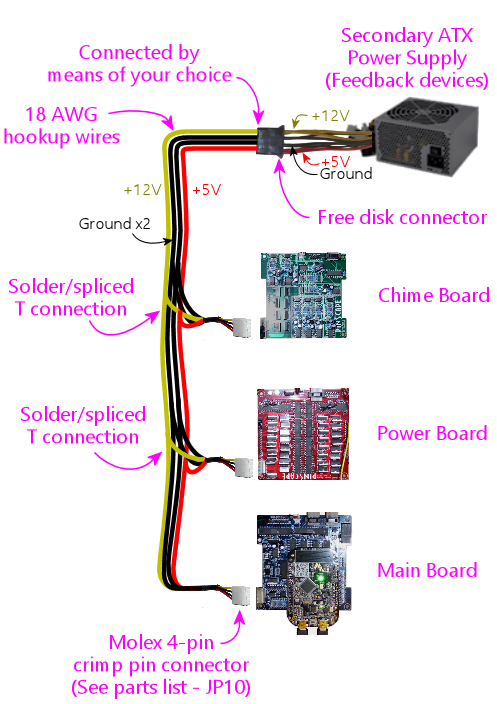
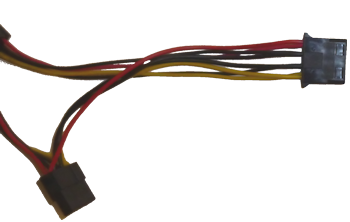
The "secondary" cable, similarly, connects to your secondary PC's
power supply at one end, and runs in a daisy-chain to each
expansion board, plugging into the "2ND PSU" connector on each
board.
Wire
To build these cables, use ordinary hookup wire. Here are the
recommended wire types:
- Primary PSU connectors:
- 22 AWG
- One black wire
- One red wire
- Secondary PSU connectors:
- 18 AWG
- Two black wires
- One red wire
- One yellow wire
Note that the secondary PSU connector uses two black wires,
which connect to the corresponding black wires in the disk connectors.
Be sure to connect both of these even though it seems redundant to use
two. The reason we use two is that it doubles the current-carrying
capacity. The black wires on these connectors carry the
combined current from all of the feedback devices, so
they can be subjected to very high currents at times. It's the same
reason the ATX power cables use two black wires - all of the current
for all of the different voltages ends up going through these wires.
For each wire:
- Cut one piece long enough to reach from the power supply to the farthest expansion board
- Cut one additional piece for each additional expansion board, long enough to reach from the main cable to that board
How to connect to the expansion boards
See the parts list for the necessary
connectors. There are two distinct connector types:
- A two-pin connector for the PC PSU (primary power supply) connections
- A four-pin connector for the 2ND PSU (feedback devices/secondary power supply) connections
These are crimp pin housings, so you have to build them by crimping
the pins onto the ends of the wires, and inserting the pins into the
housings. Full instructions are in Crimp Pins.
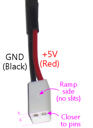
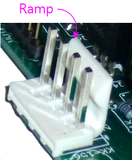
Here's the pin ordering for the two-pin primary power supply
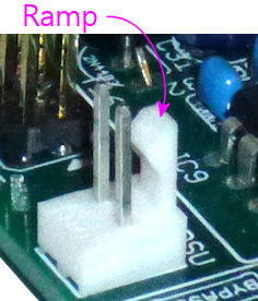
connector. To orient it properly, look for the "ramp" side, which is
the side that faces the ramp on the circuit board header when you plug
it in. (The ramp is the vertical plastic projection on one side of
the header, which ensures that you plug the connect in the right way.)
The ramp side on this connector isn't marked very clearly, but you can
identify it because it's the solid side - the opposite side has narrow
slots where the crimp pin lock tabs fit. You can also tell the
difference between the two sides by the distance to the pin openings
in the bottom: notice in the picture how the pin openings are closer
to the ramp side.
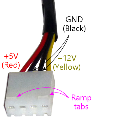
Here's the pin ordering for the four-pin secondary power supply
connector. To orient it, look for the "ramp tabs" - the little
triangular tabs sticking out on one side of the connector. This is
the side that faces the ramp on the circuit board header when you
plug it in.
Once the housings are built, you connect them to the Pinscape boards
simply by plugging them in to the matching headers. The connectors and
headers are keyed so that you can only plug them in one way.
How to connect to the ATX power supplies
One end of each of the special Pinscape power cables connects to one
of your ATX power supplies. There are several ways to handle the
connection at this end.
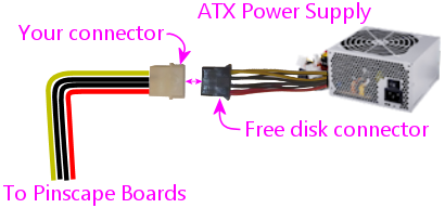
Through a disk connector plug
My preferred way to connect to each ATX power supplies is through a
free disk power connector on the power supply. This approach doesn't
require any modifications to your power supply; you just plug into
it the way you'd plug in a disk drive.
The disk power connectors are the four-pin connectors that look like this:
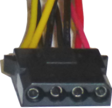
This is a standard connector - the brand name is AMP Mate-N-Lok.
(It's commonly misidentified as a Molex connector. There is in fact a
similar-looking Molex connector, but it has a slightly different plug shape
that's not compatible.) The connector that's attached to your ATX
power supply is female, so to connect to this, you need the male side:
- TE/AMP 1-480426-0 Mate-n-Lok 4-pin housing
- TE/AMP 60620-1 male crimp pins, quantity 4 per connector
These are crimp pin housings, so they require some assembly. See
Crimp Pins for details on how to build this kind of
connector.
One slight complication: the AMP crimp pins for this housing are
designed for wire gauges from 20AWG to 14AWG. That's fine for the
secondary PSU connector cabling, for which I recommend 18AWG hookup
wire. But the primary connector cabling can't be thicker than 22AWG
because of the crimp pins we use at the expansion board end! You
might find that these large AMP crimp pins don't crimp onto the 22AWG
wire tightly enough. If it won't stay in place after crimping, you
can secure it by soldering the wire to the pins. Which defeats the
purpose of the crimp pins (easy of assembly), but works.
Alternatively, you can use thicker wire (18AWG, say) at the AMP
connector end, and solder those thicker wires to the thinner 22AWG
wire needed at the Pinscape end.
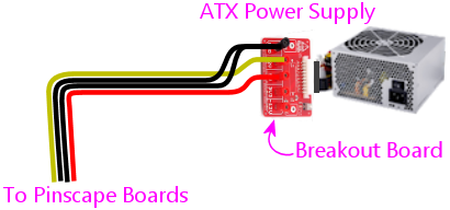
Through a breakout board
If you're using a breakout board to
access your ATX power supply's 5V and 12V connections, you should use
whatever connector type your breakout board uses. For example, if
your breakout board uses screw terminals, simply strip 1/4" or so of
wire from the end of the custom Pinscape power cable that's going to
connect to the breakout board, and screw the ends into the appropriate
terminals.
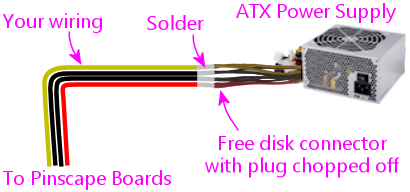
Hard-wired
The simplest way is to solder the Pinscape cabling
directly to your ATX power supply's wiring, preferably to one of the
disk power connector cables. This isn't my favorite approach, because
it permanently modifies the power supply, but it's quicker and easier
than messing around with crimp pins, and cheaper than adding a
breakout board.
To do this, chop off one of the disk connector plugs on the power
supply. That'll leave you with four bare wires you can solder to.
Strip 1/4" or so of insulation from the end of each wire. Do the same
with the wires in the Pinscape cable. Solder the ends together.
Cover the exposed solder joints with shrink-wrap tubing or
electrician's tape.
This leaves you with an ATX power supply with one less disk power
cable, and a permanently attached Pinscape power cable. You can still
plug and unplug the Pinscape ends, so there's no loss of modularity.
Frequently asked questions about the power connectors
I've helped a number of people debug problems that came down to
missing power connections, so I wanted to clarify some points about
the power wiring. Some of the confusion probably comes from the LedWiz
and some of the other arcade devices that have a bunch of connectors
that you don't really need, so people probably get used to the idea
that the connections on these controllers are mostly for "other
people" with unusual setups. Not in this case! The connectors
on these boards are for everyone. So, to answer some questions
that have come up several times:
- Do I really need to connect the 5V and 12V wires in the secondary connectors?
Yes! These power connections actually provide power to the logic chips and transistors on the board. If the supply voltages aren't connected, the logic chips and transistors won't have power, and they simply won't work.
- Do I really need the both black wires in the secondary connector?
Yes! The secondary connector provides the common ground connection for all of your feedback device power connections. When your 3A shaker motor runs, that 3A goes through these wires. When your 3A shaker motor runs at the same time as your 4A gear motor and your 2A fan, the combined 9 Amps from all of those devices goes through these wires. We use two wires because it doubles the current-carrying capacity of one wire. We need that extra capacity because of the high combined current that can result when multiple feedback devices are running at the same time.
- Do I really need to connect both the primary and secondary connectors to each board?
Yes! The two power connectors supply power to separate circuits on each board. The primary PSU connector supplies power to the "logic" circuits that connect to the KL25Z, such as the TLC5940 chips on the main and power boards, and the 555 timer chips on the chime boards. If the primary PSU connector isn't connected, none of the logic circuits receive any power, and nothing works. The secondary PSU connector supplies power to the MOSFETs that carry out the power switching, and they provide the ground connections for all of the feedback devices' power supply connections. If this connector isn't connected, the MOSFETs can't switch and the feedback devices don't have any connection to ground, so nothing works.
- Do I really have to use two separate ATX power supplies for these boards?
No. It's possible to run everything off of the single ATX power supply that's powering your PC motherboard. You do still have to connect both power cables, though - you'd just connect them both to that single ATX supply, if that's all you have.
But this is one of those cases where you shouldn't do something just because you can. The reason that we take it for granted that you're using two power supplies is that sharing a single power supply with feedback devices places too much load on your single PSU, and creates too much opportunity for electrical interference.
