Appendix 5. DOF Config Tool Device Descriptions
When you set up your cabinet with DOF, you'll want to use the
DOF config tool to map out the
physical devices in your cab. This lets the Visual Pinball
table scripts know how your physical devices relate to the
events in the game.
The Config Tool lets you make these assignments by telling it the type
of device attached to each output controller port. The tool has a
pre-defined set of standard types, so you just choose the matching
type for each device. These are all in terms of pinball abstractions,
because that's how DOF knows to connect them to events in the game.
Most of these pinball device types are self-explanatory, but some of
them are obscure, and some use virtual pin cab jargon that might not
make sense even if you're a long-time pinball fan. To help clear up
the confusing parts, below you'll find a list of all of the device
names that appear in the Config Tool, along with explanations of what
they mean and how they're usually implemented in a virtual cab.
Start Button: The lamp inside the Start button on your cab's
front panel. On most games, this either stays lit the entire time, or
lights up or flashes when there are coin credits available to start a
new game. See Button Lamps.
 Launch Button and Authentic Launch Ball: Both of
these options are for the lamp inside your Launch Ball button,
if you have one. They're both meant to be used with the same
button light, but they behave slightly differently. You get to
choose the one whose behavior you prefer. See Button Lamps.
Launch Button and Authentic Launch Ball: Both of
these options are for the lamp inside your Launch Ball button,
if you have one. They're both meant to be used with the same
button light, but they behave slightly differently. You get to
choose the one whose behavior you prefer. See Button Lamps.
The difference between the two options is pretty subtle:
- The regular "Launch Button" setting turns on the button lamp in most games whenever a ball is in the plunger chute.
- The "Authentic Launch Ball" setting only turns on the button lamp when you're playing a machine that originally had a Launch button in place of a plunger. On those machines, it reproduces the original behavior of the Launch button light on the real machine. When you're playing a game that had a plunger in the original arcade version, this setting generally leaves the Launch button light off.
For example, suppose you load Earthshaker into Visual Pinball.
The real Earthshaker has a plunger, not a Launch button, so
the "Authentic Launch Ball" light will stay off the whole time you're
playing this table. Now suppose you load Medieval Madness into
VP. Real MM machines have a Launch button instead of a
plunger. In this case, "Authentic Launch Ball" will control the
lamp using the same pattern it would on a real MM
machine. In contrast, the regular "Launch Button" setting would
turn the light on in either game whenever a ball is in the plunger chute.
The Config Tool offers both options for the sake of flexibility, to
let you customize it according to your tastes. If you want the button
to light up for most games, even games that originally had plungers,
choose Launch Button. If you want the button to faithfully simulate
the way the real machines work, choose Authentic Launch Ball.
My advice is to choose according to whether or not you have a plunger
in addition to the Launch button:
- If your cabinet only has a Launch Ball button, and no plunger, choose Launch Button. Since you don't have a plunger, you'll be using your Launch button in every game, so it's nicer to have it light up most of the time.
- If your cabinet has both a plunger and a Launch button, use Authentic Launch Ball. That's better if you have both controls, because it will make your cabinet give more prominence to whichever control is appropriate for the game you're playing at any given time. When you're playing a plunger table, the Launch button will stay dark and discretely step into the background. When you're playing a plunger-less table, the Launch button will light up whenever a ball is ready, inviting the player's attention.
- If your cabinet only has a plunger and no Launch button, there's nothing to choose, so this whole question is moot!
ZB Launch Ball: This is an unusual output in that it's a
"virtual" output only. You can ignore this for now, because it's
not intended to be connected to a physical feedback device; it's
related to the plunger setup instead. If you're curious, you
can read about it in ZB Launch Ball.
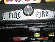 Fire Button: The lamp inside the Fire button, which is
an extra button on top of the lockbar on some real machines. This
is common on newer Stern machines, but various machines through the
years have featured similar extra controls. It's uncommon on virtual
cabinets, but some people include it for completeness. This light
turns on in some games during special modes where the button
becomes active. See Button Lamps.
Fire Button: The lamp inside the Fire button, which is
an extra button on top of the lockbar on some real machines. This
is common on newer Stern machines, but various machines through the
years have featured similar extra controls. It's uncommon on virtual
cabinets, but some people include it for completeness. This light
turns on in some games during special modes where the button
becomes active. See Button Lamps.
 Extra Ball: The lamp inside the Extra Ball light. Many real
machines from the 1990s had an "Extra Ball" or "Buy-In" button on
the front panel, usually situated below the Start button or below
the plunger. This let players buy an extra ball for a credit after
the last ball drained. This lamp turns on in most games that had
these buttons when the extra ball buy-in offer is available.
See Button Lamps.
Extra Ball: The lamp inside the Extra Ball light. Many real
machines from the 1990s had an "Extra Ball" or "Buy-In" button on
the front panel, usually situated below the Start button or below
the plunger. This let players buy an extra ball for a credit after
the last ball drained. This lamp turns on in most games that had
these buttons when the extra ball buy-in offer is available.
See Button Lamps.
10 Bumpers and 8 Bumpers: These are tactile feedback
devices that simulate the mechanical kick of a pop bumper on a real
machine. Virtual cab builders use a variety of devices to simulate
these, including "contactors" (a type of electronic relay), automotive
starter solenoids, open-frame solenoids, or even real pinball bumper
coils. Most virtual cab builders set up an array of these devices
spread across the middle and back of the playfield area so that the
sound effects are properly positioned in space.
See Flippers, Bumpers, and Slingshots.
The names "10 Bumper" and "8 Bumper" are a little misleading. A "10
Bumper" setup actually has 6 bumper devices, and an "8 Bumper" setup
really has 4 bumpers. It would be clearer if the names were
something like "10 Solenoid" and "8 Solenoid", because the "10" and
"8" don't count just the bumpers, but rather all of the
solenoid-type devices in your whole system, including two for the
slingshots and two for the flippers. So if you have two flippers, two
slingshots, and four bumpers, you have an "8 Bumper" setup. If you
have two flippers, two slingshots, and six bumpers, you have the "10
Bumper" setup.
Here's the typical "10 Bumper" device placement:
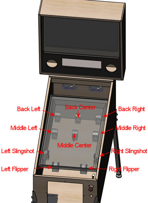
"10-Bumper" placement. The actual "bumper" simulators are
the six devices across the middle and back playfield area.
The two devices at the front are the flipper simulators,
and the two just behind those are the slingshots.
If you're using ten of these solenoid-type devices overall, and you've
arranged them roughly like this, you'd assign six of your ports as "10
Bumper" devices. The one at the back left corner is "10 Bumper Back
Left", the rear center one is "10 Bumper Back Center", and so on for
the others.
If you're building a smaller cabinet, or you just want to keep things
a little simpler, the "8 Bumper" arrangement is almost the same, but
only uses one device in the back row:
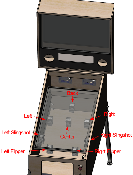
"8-Bumper" placement. The actual "bumper" simulators are
the four devices across the middle and back playfield area.
The flipper and slingshot devices are the same as in the
"10-Bumper" layout.
 Slingshot Left and Slingshot Right: The solenoid-type
devices that simulate the mechanical kick of the slingshots on a
real machine. The slingshots on a real machine are the kickers in
the rubber-band triangles just above the flippers on most pinball
tables. On a virtual cab, these are usually simulated by a pair
of solenoid-type devices (the same types of devices used to
simulate the bumpers - see above), usually placed near the front
of the playfield TV on or near the left and right walls of the
cabinet.
See Flippers, Bumpers, and Slingshots.
Slingshot Left and Slingshot Right: The solenoid-type
devices that simulate the mechanical kick of the slingshots on a
real machine. The slingshots on a real machine are the kickers in
the rubber-band triangles just above the flippers on most pinball
tables. On a virtual cab, these are usually simulated by a pair
of solenoid-type devices (the same types of devices used to
simulate the bumpers - see above), usually placed near the front
of the playfield TV on or near the left and right walls of the
cabinet.
See Flippers, Bumpers, and Slingshots.
Flipper Left and Flipper Right: The solenoid-type
devices that simulate the mechanical kick of the flippers. These
are usually placed near the front of the playfield, set in slightly
from the cabinet walls, to simulate the usual placement of
flippers on real machines.
See Flippers, Bumpers, and Slingshots.
Knocker: A solenoid device that reproduces the replay
knocker in a real cabinet. Many virtual cabs simply use actual
pinball knockers for these. They're usually placed in the backbox,
near the top left corner.
See Replay Knockers.
Shaker: A shaker motor. This is a motor place inside the
cabinet, with an off-balance weight attached to its shaft. When
activated, it makes the cabinet vibrate, creating a mini-earthquake
effect. Placement of the motor isn't critical, since the point is
to make the whole cabinet shake, but it's usually fastened to the
floor of the cabinet around the middle section.
See Shaker motors.
 Gear: A gear motor, which is just what it sounds like: a small
motor with gears attached to the shaft, placed somewhere inside the
cabinet. The function in a virtual cabinet is purely as a sound
effect device, to mimic of the sound of the small motors that are
frequently used in real machines to animate playfield elements (think
of the Thing hand coming out of its box in The Addams Family,
the rotating trunk in Theatre of Magic, or the drawbridge in
Medieval Madness). These are usually placed around the
middle playfield, slighly rear of center, to allow for a reasonable
approximation of a range of devices in real games.
See Gear motors.
Gear: A gear motor, which is just what it sounds like: a small
motor with gears attached to the shaft, placed somewhere inside the
cabinet. The function in a virtual cabinet is purely as a sound
effect device, to mimic of the sound of the small motors that are
frequently used in real machines to animate playfield elements (think
of the Thing hand coming out of its box in The Addams Family,
the rotating trunk in Theatre of Magic, or the drawbridge in
Medieval Madness). These are usually placed around the
middle playfield, slighly rear of center, to allow for a reasonable
approximation of a range of devices in real games.
See Gear motors.
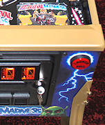
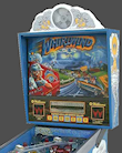 Fan: A fan that blows air at the player when activated. A
handful of real machines had these, notably Whirlwind, which
had a 4" fan on top of the backbox that turned on during multiball
and other game events. Virtual cab builders who include fans usually
put them on top of the backbox, à la Whirlwind, but
some people put them in other places, such hiding them behind
vents in the coin door.
See Fans.
Fan: A fan that blows air at the player when activated. A
handful of real machines had these, notably Whirlwind, which
had a 4" fan on top of the backbox that turned on during multiball
and other game events. Virtual cab builders who include fans usually
put them on top of the backbox, à la Whirlwind, but
some people put them in other places, such hiding them behind
vents in the coin door.
See Fans.
Strobe: A bright white light, usually placed at the back of the
main cabinet or on top of the backbox. Cab builders usually implement
these using LED floodlights meant for use on pickup truck light bars.
The strobe is essentially a virtual pinball community invention that
doesn't correspond to any common feature from real machines, although
a few real machines had something vaguely similar (notably
Flash).
See Flashers and Strobes.
 5 Flashers: The "5 Flashers" are a set of five separate bright
lights, usually implemented with high-power, full-color "RGB" LED
lamps. In real pinball machines, "flashers" were high-intensity lamps
placed around the playfield in various spots to create dramatic
lighting effects. Most pinballs from the mid 1980s had five or six of
these placed strategically around the playfield, usually enclosed in
colored plastic domes. Virtual cab builders can't easily place these
around the playfield, since our playfields are actually TVs, so we
usually position at the back of the main cabinet, or sometimes on top
of the backbox. And we usually arrange them in a simple row of 3 or 5
evenly spaced lights.
5 Flashers: The "5 Flashers" are a set of five separate bright
lights, usually implemented with high-power, full-color "RGB" LED
lamps. In real pinball machines, "flashers" were high-intensity lamps
placed around the playfield in various spots to create dramatic
lighting effects. Most pinballs from the mid 1980s had five or six of
these placed strategically around the playfield, usually enclosed in
colored plastic domes. Virtual cab builders can't easily place these
around the playfield, since our playfields are actually TVs, so we
usually position at the back of the main cabinet, or sometimes on top
of the backbox. And we usually arrange them in a simple row of 3 or 5
evenly spaced lights.
Typical "5 Flashers" arrangement: five
flasher domes in a row across the back wall of the cabinet
above the playfield TV.
The Config Tool's "5 Flashers" devices are designed for cabinets that
have a row of five of these lights. The Config Tool assumes that
your flashers are arranged in a single horizontal row, so it gives
you entries for the Outside Left, Left (which really means "Inside
Left"), Center, Right (really "Inside Right"), and Outside Right
positions.
The flashers are usually RGB devices, meaning that each one is
actually made up of three separate LEDs - one Red, one Green, and one
Blue. These three color LEDs have to be wired individually so that
they can be controlled separate. That means that a single flasher
actually acts like three separate devices on your output controller.
You have to run three separate wires to three separate port connectors
on your controller. For five flashers, you have to assign 15 ports.
The Config Tool knows all about RGB devices, but it imposes a special
rule for them: the Red, Green, and Blue ports for each device
must be consecutively numbered, and they must be in this
order: Red, Green, Blue. For example, let's consider the Outside Left
flasher. If you connect its Red LED to port 15 on your controller,
then you have to connect its Green LED to port 16, and its Blue LED to
port 17. The Config Tool doesn't give you any other way to group the
color connections, so be sure to arrange your wiring in that order for
each flasher device.
Once you've set up your port wiring in the correct Red-Green-Blue
order, the Config Tool makes it really easy to set up an RGB device.
You simply go to the port number where the Red LED of the group is
connected, and you select, say, "5 Flasher Outside Left". This
automatically assigns the whole group of three ports to the
corresponding color channels for the same device. So even though
you have to wire 15 physical channels to your 5 flashers, you only
have to make five port assignments in the Config Tool - one for
the Red channel for each flasher. The Green and Blue channels
for each flasher will be automatically assigned to the adjacent
channels.
See Flashers and Strobes.
3 Flashers: If you're building a mini-cabinet, you might
only have room for a row of three flasher lights. Choose the
"3 Flashers" devices if you're using this configuration. Assign
one set of RGB channels to each of your left, center, and right
LEDs. As with the "5 Flashers", the DOF Config Tool requires these
to be RGB devices, so you have to assign a block of three color
channels (Red, Green, Blue) to each of the three flashers.
See Flashers and Strobes.
RGB Flippers: These are for miniature RGB LEDs inside
the flipper buttons, to illuminate the buttons from within. The
Config Tool assumes that you've wired your left and right flipper
buttons together to the same output controller ports, so you just
have to assign one set of outputs for these. As with the "5 Flashers",
these are required to be RGB outputs, so a set of three consecutive
ports is required, and they must be wired in Red, Green, Blue order.
See Button Lamps.
RGB Left Magnasave and RGB Right Magnasave: These are
for miniature RGB LEDs inside your left and right MagnaSave buttons,
which are the second set of flipper-like buttons found on some
real machines and many virtual cabs. Like the flipper buttons,
these can be illuminated from within with RGB LEDs. Unlike the
flipper buttons, DOF provides separate Left and Right channel
assignments for these. The reason is that some real machines
had asymmetrical MagnaSave buttons (such as only including a left
or right button, or using different colored buttons on the two
sides), so it's desirable to be able to control the two sides
separately to replicate these asymmetries. As with the flipper
button lights, these are required to be RGB devices, so you have
to wire each Magnasave light to a block of three output controller
ports, and arrange them in Red, Green, Blue order.
See Button Lamps.
RGB Undercab Smart and RGB Undercab Complex: These are
for RGB light strips mounted on the underside of your cabinet, and
sometimes the back of the backbox, to create a glowing pool of light
around the machine. This is another case where there are two options
for the same physical device type, to let you choose which type of
programming you prefer. The "Smart" version generally uses a single,
fixed lighting color for each game. The "Complex" version changes the
colors in some games sync with game events, creating more of a light
show. Some people prefer the light show effect, while others find it
to be too distracting.
See Undercab Lighting.
"MX" devices: There are a bunch of entries in the list ending
in "MX": PF Left Flashers MX, LF Left Effects MX, etc. You can ignore
these when you're setting up your main feedback devices, because
they're only for "addressable light strips", a special type of device
that requires its own dedicated controller.
See Addressable Light Strips.
Coin: This is for the lamp inside your Coin button, if you have
a separate button for this. A Coin button isn't something you'd find
on real machines; it's a button that some virtual cab builders add so
that they can easily simulate inserting a quarter. If you're using a
standard door with coin slots, you could use the Coin output to
control the lamps in the coin slots, but there's no reason to do this
for the sake of authenticity: the coin chute lights on the real
machines are simply wired to be permanently on. In any case, the
Config Tool settings for the Coin lamp generally leave the Coin light
turned on any time a table is loaded, so it's not much different from
wiring the lamp to be always on.
See Button Lamps.
How to play: This is for the lamp inside another virtual-only
button, this time a "How to play" button. This button is meant to
display a game's instruction card when you're navigating an older menu
system like HyperPin. This kind of extra button was fashionable for a
while in the early days of virtual pinball, but it's more common now
for cab builders to avoid buttons that aren't common on real pinball
machines. And the newer menu systems like PinballX don't need
dedicated buttons like this, since they expose extra features like
this with on-screen menus instead of extra buttons.
See Button Lamps.
Genre: This is for yet another virtual-only button lamp, in
this case a "Genre" button that lets you switch categories in older
menu systems like HyperPin. Like the "How to play" button, this
button isn't common on more modern virtual cabs, since the newer menu
systems don't need it.
See Button Lamps.
Exit: The button lamp inside the Exit button. "Exit" is the
one virtual-only button that you really can't do without; it stops
the current game and returns to the menu system. You need a special
button for this function because real pinball games simply
don't have a concept of "exiting" to a menu system.
See Button Lamps.
Custom Output 1-4: These are extra outputs available for
you to assign to any unique feedback devices in your cabinet that
don't correspond to anything else in the Config Tool lineup. The
standard Config Tool database doesn't do anything at all with these
outputs, but it lets you define your own rules for triggering them
during game play.
Be warned that it can be a lot of work to set these up, because you
have to manually create rules for them in every table where you want
to use them. See Customizing a table's DOF effects for details.
Custom RGB 1-2: These are just like Custom Output 1-4
above, but in this case they're for you're custom RGB lighting devices. That
is, devices with color channels for Red, Green, and Blue.
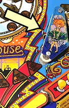
Bell: A large mechanical bell, such as the one on the top of
Fire's backbox, which some games use for dramatic effect.
This type of bell is meant to produce a loud,
deep note like a church bell. See Chimes and Bells.
Chime Unit High Tone through Chime Unit Low Tone:
These are for a traditional chime unit with three chime bars, of
the sort used in many electromechanical pinballs of the 1960s. You
can install a real chime unit (or a replica) for more authentic
re-creations of the sound effects in older games.
See Chimes and Bells.
Chime Unit Extra-Low Tone: A fourth chime
bar, if you have a four-bar chime unit like those used in some Bally
machines in the late 1970s. See Chimes and Bells.
Chime 5: This is for a fifth chime bar, which (as far as
anyone can tell) is a DOF extension that doesn't correspond to real
chimes in any real machines, but can be used to add extra variety
to EM game play by adding a fifth chime tone. See Chimes and Bells.
Shell Bell Small and Shell Bell Large: These are
for a pair of shell bells, which are similar to chime units but
use circular ringing elements for a different tonal effect. Some
EM machines from the 1960s and 1970s used this instead of chime
bars. See Chimes and Bells.
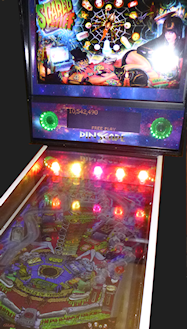
Repeating Bell: A bell that mechanically strikes repeatedly as
long as it's energized, like the bell in an old-fashioned telephone or
in a fire alarm. A few games (Space Shuttle, Taxi) use
repeating bells for sound effects during play. See Chimes and Bells.
Hellball Motor and Hellball RGB: These outputs are
designed to control a Varytec Hellball, which is a sort of disco party
ball. The Motor output controls motion, the RGB output controls the
spotlight color.
