59. Flippers, Bumpers, and Slingshots
Real pinball machines are mechanical contraptions with lots of moving
parts. It's what makes them stand apart from just about every other
kind of arcade game. When you translate pinball into a video game,
you lose that physicality. In a virtual pin cab, you can bring back
some of the mechanical feel of the real thing by adding similar moving
parts that can be actuated in sync with the game action.
The moving parts on a real machine that produce most of the tactile
experience for the player are the ones controlled by solenoids:
flippers, slingshots, bumpers, kickers. All of these are driven by
powerful magnetic coils that propel the metal parts at high speed.
The kick of the solenoids is palpable while playing. This chapter is
about reproducing that tactile solenoid effect in a virtual cab.
How many? Where do they go?
It's up to you which devices to include in your setup. The common
setups, which DOF supports most readily, use two devices to simulate
flippers, two to simulate slingshots, and four to six devices to
simulate pop bumpers.
Flippers: The most basic solenoid setup uses just two
solenoids, one for each flipper. These should be positioned near the
location where the actual flippers appear in the video presentation,
near the bottom of the TV. You can mount these inset a bit from the
sides of the cabinet, where the actual flipper solenoids would be on a
real machine, or you can mount them directly to the cabinet walls. If
you're using slingshot solenoids in addition to the flippers, you
might want to use the inset positioning for the flippers, and position
the slings further apart, to make the sounds more noticeably separated
in space.
Slingshots: These go just behind the flipper devices. Most
people mount these directly to the side walls of the cabinet, since
real slingshots are also close to the walls.
Bumpers: There are two common configurations for bumpers.
The "deluxe" arrangement uses six devices, arranged as a row of
three across roughly the middle of the playfield TV, and a second
row of three closer to the rear of the TV. This provides devices
at enough different places that DOF can do a good job of placing
each sound effect close to its simulated origin in the game.
The other common arrangement uses a single row of three across
the middle of the TV, and one more near the rear center.
DOF refers to these two common bumper configurations as "10-Bumper"
and "8-Bumper" setups. That's a bit confusing, because it doesn't
really mean bumpers. In both cases, two of the devices
are flippers and two are slingshots. So what DOF really means
is "10-Solenoid" and "8-Solenoid".
Here's what the two arrangements typically look like in a cab.
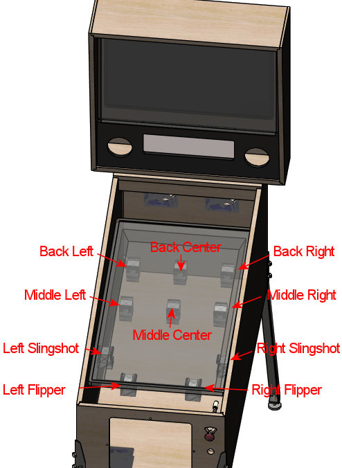
"10-Bumper" placement. The actual "bumpers" are
the six devices across the middle and back playfield area.
The two devices at the front are the flippers,
and the two just behind those are the slingshots.
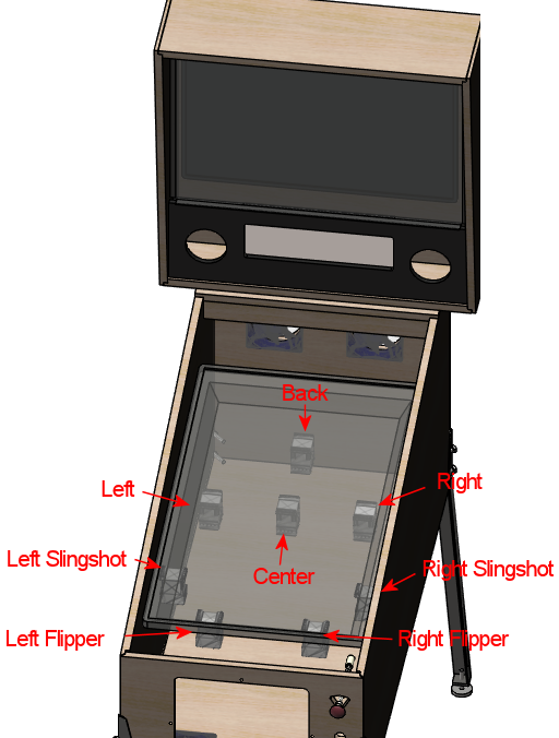
"8-Bumper" placement. The actual "bumpers" are
the four devices across the middle and back playfield area.
The flipper and slingshot devices are the same as in the
"10-Bumper" layout.
Parts
The most effective way to reproduce the sensory effects of a pinball
solenoid is to use some of kind of solenoid.
In a real pinball machine, they have to use a specific mechanism for
each job, because each mechanism has to do the actual work of
propelling the ball (or whatever it's meant to do). In a virtual cab,
we don't have that constraint. Our devices don't have to actually do
anything physical in the game; they just have to produce the right
sensory impression. So we're free to substitute anything that sounds
and feels similar. That opens up our options and lets us consider
other properties when we're selecting devices, such as cost, size,
durability, and power needs.
If you open up the field to consider anything with a solenoid in it,
you have an overwhelming number of options. Fortunately, people have
been building pin cabs for long enough now that a few winning options
have emerged, so you won't have to spend months doing research on
this; you can just pick one of the common solutions below. Like most
pin cab features, everything has some tradeoffs, so there's not a
perfect one-size-fits-all solution. We'll give you the pros and cons
of each to help you decide.
Note that you don't have to settle on a single device type! Many pin
cab builders do use one device type for everything, but others think
it's a plus to use different devices for different roles, so that each
type of device sounds a little different. For example, you might use
the Siemens contactors for the flippers, and starter relays for the
bumpers and slingshots.
Contactors
A contactor is a type of electrically controlled switch used in
high-power applications, such as controlling industrial equipment or
large appliances like air conditioners. "Contactor" is just
another word for "relay" - they're fundamentally the same thing - but
they call it a contactor when it's the higher power type.
On the inside, a contactor is a mechanical switch controlled by a
solenoid. The solenoid moves a set of mechanical switch blades when
energized. Because of the high power that a contactor is designed to
handle, the switch blades have to be hefty, and they have to move
across a wide gap when switching.
It's that big moving switch element that makes contactors useful for
our purposes. The large moving parts make a nice "thunk" when the
device switches on and off, strong enough to resemble a pinball
flipper, slingshot, or bumper.
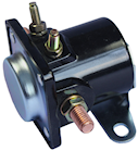
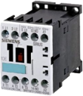 What to buy: The type of contactor that's popular with pin cab
builders is made by Siemens. One particular known quantity that many
cab builders use is Siemens model number 3RH1140-1BB40 (pictured at
right). It's safest to look for that exact part, but Siemens makes a
large number of similar devices, and I suspect that any Siemens model
that physically resembles this one will have substantially the same
component parts inside and will produce similar sensory effects.
What to buy: The type of contactor that's popular with pin cab
builders is made by Siemens. One particular known quantity that many
cab builders use is Siemens model number 3RH1140-1BB40 (pictured at
right). It's safest to look for that exact part, but Siemens makes a
large number of similar devices, and I suspect that any Siemens model
that physically resembles this one will have substantially the same
component parts inside and will produce similar sensory effects.
Many other types of contactors are also available from other
manufacturers, so there are undoubtedly many more options out there
that would work. However, there's no reason to assume that any random
contactor would sound "right". If you're considering another device,
ask in the forums to see if anyone else has tried it; or try it
yourself if you want to be a pioneer, but ideally buy it from someone
who will let you return it if it doesn't do the job.
Cost: You can buy these devices new, but you shouldn't:
they're $50 and up apiece new. Given the performance tradeoffs,
they're not worth the money; if you have that kind of budget,
real pinball parts would be a far better investment. So you should
instead buy them used on eBay, where they can be found for about $10
apiece. You might have to be patient to find them at a reasonable
price, since they seem to be a fairly low-volume item on eBay.
Power supply: The Siemens contactors require 24VDC power.
That's not available from a computer ATX power supply, so you'll need
a separate power dedicated 24V supply. See Power Supplies for Feedback
for advice.
The Siemens contactors draw about 400mA each. I'd plan on sufficient
power for three or four of them to fire simultaneously, so be sure
your 24V power supply is rated for at least 2A (equivalent to 48W).
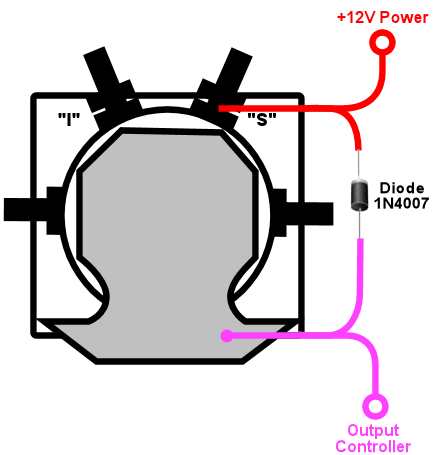
Wiring: Here's how to hook up the typical Siemens contactors:
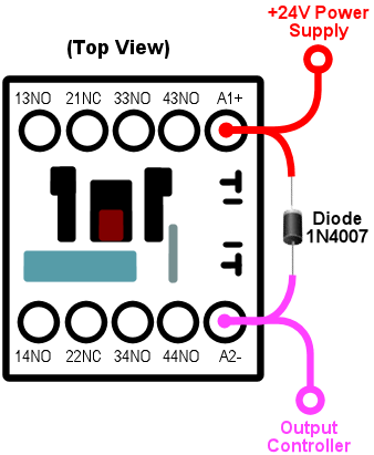
Note that most of the terminals on the contactor are left unconnected.
The other terminals are all intended to be wired to whatever circuits
the contactor is controlling, but in our case, we don't control
anything at all with the contactor. It's just there for the sound
effect it makes when it switches on and off, so we only connect
the terminals that control its coil, typically A1 and A2 on the
Siemens devices.
The diode is required to protect the output controller and computer
electronics from noise from the magnetic coil inside the contactor.
See Coil Diodes. The stripe on the diode must connect to the
positive (+) power side.
Pros: The biggest "pro" with contactors is that they're happy
to be left in the "on" position indefinitely. That's not at all true
of most solenoids: most solenoids will overheat if left on for long
periods, and many can only tolerate a couple of seconds at a time.
For simulating flippers, the ability to stay on for long periods is
critical, because the player could hold the flipper button
indefinitely to trap a ball.
The tonal quality of audio/tactile effect of the Siemens contactors is
another plus. It's a nice solid mechanical "thunk" that creates the
impression of a large device.
Other good features: they're compact, self-contained, easy to install,
run on fairly low DC voltages (the Siemens devices referenced above
run on 24VDC), and use relatively little power (about 350mA for the
common Siemens device).
Cons: The biggest negative is that the effect is far weaker
than a real pinball solenoid (even though the tonal quality is good).
Also, they require 24V, which means you have to add an extra power
supply for them. The Siemens devices are pricey, unless you buy them
used, and used ones sometimes have a lot of wear that greatly reduces
the strength of the "thunk" effect, which is the whole point for our
purposes. Used ones might not be entirely reliable, either; a couple
of my own Siemens contactors are intermittently "sticky", where
they'll stuck in the on or off position for a while and won't make any
noise. I've heard from other people seeing the same problem.
Recommendation: The Siemens contactors are a popular way to
implement the simulated flippers and other solenoids because they're
simple to install and they won't overheat if left activated for long
intervals. The tolerance for long activation times makes them especially
attractive for flipper effects. They're the best bet if you want to
keep things simple. But the effect isn't nearly as strong as the real
thing, so if realism is a high priority, look at other options.
Automotive starter solenoid relays
This is another kind of high-power relay, in this case specific to
cars. Starter solenoids are used in automotive engine starting
systems; they switch the high-current connection between the battery
and the big solenoid that cranks the engine when you turn the ignition
key. As such, they have very much the same purpose as contactors -
switching high-power loads through a relay switch - and similar
construction.
Like contactors, these have big moving parts inside that create a nice
"thunk" effect when actuated. The effect is similar in tonal quality
to the Siemens contactors, and it's often quite a bit stronger, but
usually not as strong as real pinball coils.
Starter relays are cheaper and easier to find than the Siemens
contactors. Many types sell for under $10 at auto supply stores,
eBay, Amazon, Wal Mart, and other big retailers. Like the contactors,
they're self-contained and easy to install.
Unlike contactors, these devices will overheat if energized for
extended periods, so they're not ideal for flippers. You might be
able to use them for flippers if you take special precautions, such as
using Flipper Logic (see below).
Overheating is less of a risk when you use these devices for bumpers
and slingshots, since those typically only fire in brief bursts in
normal play.
Reliability is also a concern. If you think about it, these devices
aren't typically fired all that often in their intended application of
starting a car. A pin cab will subject them to much heavier use than
the manufacturers presumably expect (and design for). Some people on
the forums have reported that they need to replace these as frequently
as every few months, which I'd find overly frustrating. But I'm sure
the durability varies a lot according to how you use your cab and
which specific devices you buy.
 What to buy: The type most often mentioned on the forums is the
Ford SW3 type (pictured at right). As with the contactors, numerous
other options are available, but this one is a known quantity
that other pin cab builders have found to work well.
What to buy: The type most often mentioned on the forums is the
Ford SW3 type (pictured at right). As with the contactors, numerous
other options are available, but this one is a known quantity
that other pin cab builders have found to work well.
Power supply: Almost every automotive device runs on 12V DC
(but as always, check the product documentation or seller page to
confirm details for the actual product you buy). You can use the 12V
output from your secondary ATX power supply. Note that these devices
place a large load on the power supply - about 6A, or 72W - so make
sure you have a powerful enough 12V supply, and don't connect them to
the same ATX power supply running your computer motherboard. When
calculating power needs, take into account that there will be times
during normal play when several of the devices fire simultaneously, so
multiply the amps/wattage rating by three or four to figure how much
total power you might need. See See Power Supplies for Feedback.
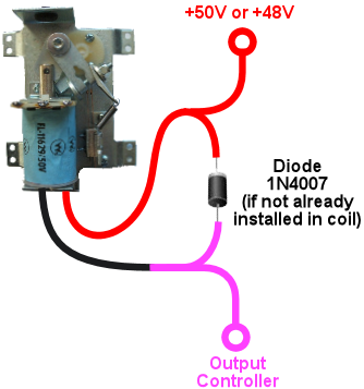
Wiring: For the Ford SW3 type commonly used, the wiring
plan looks like this:
On the Ford SW3 type, you'll find four screw terminals sticking
out from the body of the device. The ones on top (in the orientation
shown above, anyway) should be labeled "S" and "I". The ones sticking
out from the sides aren't typically labeled. In addition, the large
metal plate that looks like a mounting bracket is indeed a mounting
bracket, but it's also the electrical ground connection for the
device. The terminals of interest for pin cab use are the one
labeled "S" and the mounting bracket/ground plate.
If your solenoid isn't labeled like the Ford type above, you'll have
to figure out which terminals are which. On any automotive device,
you can count on any exposed metal on the outside being wired to the
electrical ground, so look for an unpainted mounting plate or a socket
for a mounting bolt. Now get out your multimeter. Set it to measure
resistance. Connect one probe from the meter to the ground point
(that exposed metal or mounting plate or whatever), and use the other
probe to measure the resistance to each of the other terminals, one at
a time. One terminal should have a low but non-zero resistance,
probably something like 3 or 4 ohms. That should be the +12V coil
terminal - the one that corresponds to the "S" terminal on the Ford
devices.
Connect +12V from the secondary ATX power supply to the "S" terminal.
Wire the mounting bracket to an available port on your output
controller.
The diode is required to protect the output controller and computer
electronics from noise from the magnetic coil inside the contactor.
See Coil Diodes. The stripe on the diode must connect to the
positive (+) power side.
These are high-power devices. Do not connect them directly to an
LedWiz output; you'll need some kind of booster circuit or relay with
an LedWiz. If you're using Pinscape expansion boards, you can connect
these directly to any power board port or chime board port.
Pros: Inexpensive, readily available, self-contained, easy to
install, run on 12V DC power. The sound effect they produce has a
good tonal quality, and it's stronger than the Siemens contactors
(though probably weaker than real pinball solenoids).
Cons: They're not designed for continuous activation, so they
shouldn't be used for flippers without special precautions. Some
types might not be durable enough to last more than a few months with
the heavy use they get in a pin cab. For most starter relays, the
effect isn't as powerful as real pinball solenoids.
Recommendation: These are a good choice for everything except
flippers, and they can even be used for flippers if use something like
the Pinscape "Flipper Logic" feature to reduce hold power. Many
people think they sound more realistic than the Siemens contactors.
Durability is the main drawback; some people on the forums have had
to replace them after only a few months. Given their low cost,
though, that might be an acceptable risk, as long as your cab
allows easy maintenance access.
Real pinball mechanisms
If you want maximum realism, you can use real pinball assemblies for
flippers, slingshots, and bumpers.
This is rarely done, but not unheard of. A few cab builders on the
forums have reported going this route. It has a number of challenges
compared to the other methods:
- It's really expensive. The relevant pinball assemblies run about $50 each, so a full set (two flippers, two slings, six bumpers) comes to about $500.
- The assemblies take up a lot of room in the cabinet.
- They require a high-voltage (50V), high power (600W) power supply. That's expensive, and many pin cab builders are uncomfortable working with such hazardous voltages.
What to buy: Buy these at any pinball supplier (Pinball Life,
Marco Specialties). You can also buy them used on eBay, but my
standard warning about used pinball parts on eBay applies: they'll be
beat up and the sellers all think you're an idiot who wants to pay new
prices for old parts. At least price the new ones first so you know
whether an eBay bargain is really a bargain.
The key word when searching the pinball vendors is "assembly":
- "Flipper assembly" (e.g., Williams reference C-13174-L, C-13174-R)
- "Slingshot assembly"
- "Bumper assembly" (e.g., Williams reference A-9415-2, B-9414)
Important note on flippers: Real flipper assemblies from the
1980s and 90s should have "dual coil" arrangements. You won't
actually see two separate coils - the two coils are wound around a
common core and look like a single coil. But you should see three
terminal wires coming out of the coil. The flipper assembly should
have an end-of-stroke switch that diverts power from the high-power
"lift" coil to the low-power "hold" coil when the flipper reaches the
end of its arc.
The dual-coil arrangement makes it safe to hold the flipper button
on for long periods. The lower-power hold coil is specifically
designed for continuous activation without overheating.
I mention all of this because some newer Stern assemblies don't
use the dual-coil design and aren't safe to use in a virtual pin cab
without special software provisions. If you use one of these newer
assemblies, it's critical that use something like the Pinscape Flipper
Logic feature (see below) to
reduce power to the flipper coil when it's held on. Because of this
additional complication, I'd recommend avoiding the Stern assemblies
and using a traditional dual-coil Williams/Bally assembly. That
should be safe to use with any controller without any additional setup
work, since the hold power reduction is handled directly in the
flipper assembly hardware itself.
Cost: About $50 per assembly. A full "10-Bumper" setup (in
DOF parlance - two flippers, two slings, six bumpers) is about $500.
Power supply: Real pinball coils in modern machines require 50V
DC power supplies. Most of them draw 3-5A. To allow for multiple
devices firing at once, you should plan on a minimum 10A (500W)
capacity.
50VDC power supplies are expensive hard to find. It's easier to find
a 48V supply, which will work about as well. 48V supplies are widely
used for LED lighting applications; you can find them in the
500W range on eBay for about $50.
Warning! 50V (or 48V) is a hazardous high voltage that can cause
electric shock. With most of the pin cab output controllers
(including LedWiz and Pinscape), the controller requires you to wire
solenoids so that one terminal is connected directly to the "+" power
supply voltage. This means that +50V is always present at one
terminal of each coil, even when the coils are off. Real
pinball machines have a hard-wired safety interlock switch in the coin
door that cuts off all coil power to the playfield when the coin door
is opened, to protect an operator from shock hazard while working
inside the cabinet. If you install real coils and a 50V supply, I'd
strongly recommend using a similar safety interlock. The switch
should disable the +50V power supply when the door is open.
Wiring: Each coil will have two terminals for the power
connections. Connect these following the generic output device wiring
plan (see Feedback Device Wiring).
Many of the flipper, bumper, and kicker assemblies for modern machines
include diodes pre-installed on the coils. If a coil is already
installed, it should have markings for the "+" and "-" wires. This is
often by wire color: red is "+" and black is "-".
If a diode isn't already installed, you must add one. See
Coil Diodes. When a diode isn't present, the coil itself will
be unpolarized, so the order of the wires doesn't matter. Just be
sure that the diode you add is installed with the correct polarity.
If you're using an LedWiz, these devices require some kind of booster
or amplifier, because they use much more power than an LedWiz can
handle. If you're using Pinscape expansion boards, you can connect
these to any Power Board or Chime Board port.
I'd recommend using the Pinscape Chime Boards, if you have them, for the
bumpers and slingshots (but not for the flippers). Those coils
will overheat and melt if they get stuck on by a software fault. If
you don't have any Chime Boards but you're using the Pinscape
software, use the Flipper Logic feature (see
below) to cut off device power if
a port gets stuck on, by setting the "hold power" to 0%.
Pros: Not merely realistic - real.
Cons: Expensive; take up a lot of space; vulnerable to
overheating if they get stuck on; require high-voltage power supply;
electric shock hazard.
Recommendations: The ideal solution, if cost is no object and
you're willing to work with the high voltage.
Open-frame solenoids
 The core element of every solenoid-based pinball device is the
solenoid itself, so some cab builders bypass the various devices built
around solenoids (like the contactors and starter relays
mentioned above) and just use standalone solenoids. You
can find options on eBay, and from hobby robotics suppliers like
Adafruit and Sparkfun.
The core element of every solenoid-based pinball device is the
solenoid itself, so some cab builders bypass the various devices built
around solenoids (like the contactors and starter relays
mentioned above) and just use standalone solenoids. You
can find options on eBay, and from hobby robotics suppliers like
Adafruit and Sparkfun.
Plain solenoids don't seem to be widely used on pin cabs, and many of
the people who have tried them seem to be dissatisfied with the
results, judging by the forum discussions on the subject. I think
it's possible to create a good effect with a plain solenoid, but it's
much more challenging than with the pre-made devices like contactors
and starter relays. There are two main reasons for this.
The first is cost. Many pin cab builders who use plain solenoids do
so because they think it's a cheaper way to accomplish these effects.
You can find cheap solenoids, but the cheap ones tend to be small toy
solenoids that aren't nearly as powerful as pinball coils. The
effects they produce will be correspondingly small and unimpressive.
They'll just make metallic clicks. If cost is your main concern,
you're probably going to do better with something like a starter
relay.
The second challenge is that pinball assemblies we're simulating
aren't just big solenoids. They're big solenoids with other
moving parts attached. Typically big, heavy, metal parts. Those
other parts are integral to creating the right sensory effect. If you
want to produce a convincing effect, you'll have to contrive your own
additional moving parts similar to what's in the pinball assemblies. This is what
makes the contactors and starter relays so plug-and-play: they have
their own built-in moving parts that happen to produce effects similar
to what we're after.
I think this can be a promising avenue to pursue, but moreso if you're
willing to buy somewhat more expensive parts and do some
experimentation to find the right combination of attached parts to
produce the right effect.
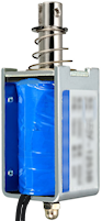
What to buy: On eBay, look for "open frame solenoid". I'd
avoid the small 12V devices; those are little toy solenoids that will
just sound like metallic clickers. Look for something 24V or above.
Sparkfun sells a 36V solenoid that a couple of people on the forums
have mentioned favorably.
Cost: $5 and up. The Sparkfun 36V device sells for about $20
as of this writing.
Power supply: Varies by device. Check the specs on what
you buy to determine what voltage you need.
If you have to buy an additional power supply, pay attention to the
Volts and Amps required by the device. Make sure the power supply has
a voltage that is the same as the solenoids, and that it provides
at least the required amperage. If you're using multiple
devices of the same type, the power supply will need to provide enough
power for several of the devices simultaneously; I'd multiply the
solenoid amperage by 3x or 4x to get a suitable minimum.
If you see specs in Watts for either the solenoid or power supply, you
can convert between Watts and Amps using this formula:
Watts = Volts × Amps
Wiring: The solenoid should have two wires attached.
Solenoids aren't polarized, so the order of attaching the wires
doesn't matter. Connect one lead to the (+) supply voltage
(use the correct voltage for the solenoid), and connect the
other to your output controller, as shown below.
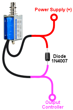
The diode is required to protect the output controller and computer
electronics from noise from the magnetic coil inside the contactor.
See Coil Diodes. The stripe on the diode must connect to the
positive (+) power side.
Pros: Many options are available; infinite customization
possibilities.
Cons: Sensory effects are less predictable than with contactors
or starter relays; you might have to experiment with several devices
and several mounting styles to get a satisfactory effect. More
complex to set up than contactors or starter relays if you want to
contrive additional moving parts to improve the sound effect. Smaller
devices will produce weak, tinny effects. Most solenoids will
overheat if actuated for more than a couple of seconds at a time, so
special measures (such as Flipper Logic) might be needed, especially
when used for flippers.
Recommendations: If you're thinking of using cheap eBay
solenoids to save money, I'd reconsider: you'll probably be unhappy
with the results and end up replacing them with something better, so
your total cost will be higher than if you just started with something
better. But plain solenoids might work for you if you're willing to
buy more expensive ones with more force, and you're willing to do some
extra work to improvise additional moving parts to simulate the action
of the full pinball assemblies.
DOF setup
In the DOF Config Tool, go to your
Port Assignments page. Find the numbered ports where you wired
your solenoid-type devices. Assign each one to the appropriate
output device.
If you're using a full 10-device setup (see the diagrams above):
- Flipper Left/Right
- 10 Bumper Middle Left/Center/Right or Back Left/Center/Right
- Slingshot Left/Right
If you're using an 8-device setup:
- Flipper Left/Right
- 8 Bumper Left/Center/Right/Back (if you're using an 8-device setup)
- Slingshot Left/Right
"Flipper Logic"
If you're using a Pinscape controller, a special feature is available
to help avoid overheating devices that aren't designed to be activated
for long periods. This isn't necessary with contactors or most real
flipper assemblies, since those are specifically designed to tolerate
continuous activation. It's useful for almost everything else: all
other standard pinball coils, automotive starter relays, and
miscellaneous open-frame solenoids.
The idea behind Flipper Logic is to simulate the way real pinball
machines solve the overheating problem for their flipper coils.
Real flipper coils would have the same overheating issue as our
substitutes if they didn't take special measures. On older pinball
machines, the special measure is that they use two separate coils in
the flipper. A high power "lift" coil provides the initial jolt of
power to flip the flipper and propel the ball, and a low-power "hold"
coil takes over as soon as the flipper is all the way up. (This isn't
obvious looking at them, because the two coils are wound into a single
body. But electrically, there are two coils there.) In the real
machines, an end-of-stroke switch in the flipper mechanism redirects
power from the lift coil to the hold coil.
In some newer Stern machines, they keep the hardware simpler by using
a single high-power coil, and solve the heating problem through
software, by modulating the power using PWM controls. When you press
the flipper button, the software initially applies full power to the
flipper (simulating the "lift coil" power). If you continue to hold
the button for more than a brief time, the software automatically
reduces the power through PWM (simulating the lower "hold coil"
power). The lower power is enough to keep the flipper flipped, but
it's low enough that it won't overheat the coil even if it's held on
for a long time.
Flipper Logic works like the newer Stern machines, reducing the power
to the port after a brief period at full power. This makes it
possible to use more types of devices as a flipper substitutes, by
avoiding the overheating problem common to many solenoids.
You can activate this feature on a port-by-port basis, for any
PWM-capable port. To activate it:
- Run the Pinscape Config Tool
- Go to the Settings page for your controller
- Scroll down to the Output Ports section
- Click the flipper icon (
 )
at the right side of the port you want to set up
)
at the right side of the port you want to set up
This lets you enter two parameters: Initial Time and Hold Power. The
Initial Time specifies how long the port receives full power each time
it's activated. You can adjust this from 50ms (1/20 of a second) to
800ms (0.8 seconds) in 50 millisecond increments. The Hold Power is
the PWM power level that's provided to the port after that point, as
long as the port is held on. This can be adjusted from 0% to 100% in
increments of about 7%.
To determine the proper reduced power level for a device, you'll have
to experiment with it. Each device is different. Start at the lowest
non-zero setting. Try the coil: turn it on and leave it on. If it
actuates and then returns to the rest position after about a second,
the power is too low, so try the next higher setting. Repeat until
the device actuates and remains actuated as long as the port is on.
Caution: always monitor the device for heating! Once you find a
setting that's high enough to keep the device actuated, you have to
verify that it's not too high a setting that overheats the
device. It's possible that some devices don't have a safe operating
zone at all - that is, a power level where they'll stay actuated and
won't overheat. You should be able to monitor the device by touch:
if it gets hot to the touch, turn if off immediately, since it's
heating too rapidly and will probably overheat if you leave it on.
If you can leave it on for a couple of minutes without having it
get hot to the touch, it's probably in thermal equilibrium, meaning
it should be safe to leave on in that state indefinitely.
Flipper button feedback control
One question that a lot of new pin cab builders ask on the forums is:
how do I make the flipper buttons control the feedback solenoids for
the flippers? In other words, how do I wire it so that pressing the
flipper buttons activates the flipper solenoids?
There are two ways to go about this. The way that most people do it
these days, which I consider the correct way, is to let DOF handle it.
Happily, this is also the easiest approach, because it doesn't require
any extra wiring or any extra configuration beyond the normal DOF
setup you're going to do anyway.
The older way of handling this, which people did before DOF came
along, was to hard-wire the flipper buttons to the flipper solenoids.
This might seem simpler at first glance than the DOF approach, since
it's just a directly wired connection. But it's actually more
complicated to build! Some extra parts are required because you have
to isolate the higher voltage that the solenoid uses from the low
voltage that the key encoder uses. So DOF takes less work and fewer
parts, assuming you're going to use DOF anyway. The only reason to
use the hard-wired approach is if you're not going to include a DOF
controller.
The thing I particularly like about the DOF approach, apart from
its simplicity, is that it does a better job of simulating
real pinball machines. If you think about how a real pinball machine
works, the flippers only fire when the game allows them to fire - not
between games, not after a TILT condition, etc. If you use the
hard-wired approach, the flipper solenoids will end up firing every
time you press the buttons, so the feedback effects won't always
match the on-screen simulation. With DOF, they'll always match.
The modern way: let DOF handle it
If you're using DOF, you don't have to do any extra
work for flipper effects. Just set up DOF, and the flipper solenoids
will work just like all of the other DOF effects. DOF will take care
of activating the flipper devices whenever the on-screen flippers flip
in a DOF-enabled game. The wiring for the flipper buttons and
solenoids is exactly the same as for every other type of button and
every other type of feedback device: wire the flipper buttons to your
key encoder, just like all of your other buttons, and wire the flipper
solenoids to your output controller, like your other feedback
devices.
If you're trying to picture how the flipper solenoids actually operate
with a DOF setup, here's the sequence of events:
- You press the flipper button, closing its switch
- The flipper button switch signals the key encoder
- The key encoder sends a "Flipper Button Pressed" keyboard event to the computer
- Visual Pinball (or whatever simulator you're using) gets the "Flipper Button Pressed" key event and fires the simulated flipper in the game
- DOF sees the simulated flipper event, and sends a FLIPPER SOLENOID ON command to the output controller
- The output controller activates the output port wired to your flipper solenoid
- The flipper solenoid fires
This approach is better than hard-wiring the solenoid for two reasons.
First, it keeps the wiring simpler. The flipper button switch is only
wired to the key encoder, and the flipper solenoid is only wired to
the output controller - exactly the same wiring as for all of your
other buttons and feedback devices. Second, it allows full software
control over the flipper. That's the way it works on a real machine:
try walking up to a real pinball machine some time and pressing the
flipper button while GAME OVER is showing on the display. Does
anything happen? No, of course not: the flippers are dead when a game
isn't in progress. By wiring the flipper solenoids through the output
controller, you'll get exactly the same effect. Hard-wired flipper
solenoids would fire every time you press the buttons, whether or not
a game was in progress.
What about latency? When DOF was new, and people started switching
over to the DOF approach, there was some worry about the extra
software steps adding a noticeable lag time between pressing the
flipper buttons and hearing the feedback effects. Fortunately, it
turns out that DOF is fast enough that this isn't a problem. You
could measure the added latency using lab equipment, but it's not
enough to be perceptible to a human. The human nervous system has
a latency perception limit of about 30 milliseconds, and DOF in
a properly working system is comfortably faster than that.
The old-fashioned way: hard-wire the buttons to the solenoids
If you're using DOF, you should ignore this section, because there's
no reason to even consider hard-wiring the flipper buttons to the
flipper solenoids. However, if you're not using DOF, you can get some
very basic feedback effects by wiring your flipper buttons to your
flipper contactors or solenoids, so that pressing the buttons directly
activates the solenoids.
At first glance, it seems like it would be dead simple to wire the
buttons to the solenoids. The complication is that you also need to
wire the buttons to your key encoder, so that pressing the buttons
sends key presses to the PC, to operate the simulated flippers in
Visual Pinball and other pinball software. That dual wiring makes
things more complex because of the different voltages used in the key
encoder and the contactor or solenoid. The higher voltage needed for
the contactors or solenoids would damage or destroy the key encoder if
you wired both of them together directly. Instead, we have to isolate
the two voltages, so that the solenoid voltage doesn't damage the key
encoder.
To isolate the voltages, we can use something called an "optocoupler".
That's a sort of solid-state relay that lets the voltage in one
circuit control a separate circuit with a different voltage, while
keeping the two voltages separated and isolated from one another.
Which is exactly what we need in this case.
If you've tinkered with electronics before, you might be more familiar
with regular mechanical relays, and you might be tempted to go with a
mechanical relay to keep things simpler. That would work, but I don't
recommend it, because mechanical relays are fairly slow. Slow enough
to cause an annoying amount of lag time in the software every time you
press the buttons. Mechanical relays also tend to wear out with heavy
use. Optocouplers are better because they're very fast and last a lot
longer.
Here's the basic circuit design that should work for any of the common
key encoders.
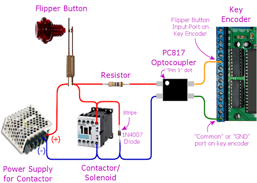
If you trace through the circuit, you'll see that the flipper button
is wired so that it activates both the contactor and the optocoupler
when pressed. Activating the contactor makes it fire, so you'll get
the flipper feedback effect whenever you press the button. Activating
the optocoupler completes the circuit on the key encoder side, so
pressing the button will also send the key press for the flipper
button. So whenever you press the button, you'll simultaneously hear
the flipper feedback effect and send the key press to the PC. The
optocoupler is the key to making both devices work together, because
it uses the higher voltage on the solenoid side to control the key
encoder side, but it does so without allowing the higher voltage to
reach the key encoder side.
The diode is needed to protect the rest of the circuit from the
voltage surge effect from the contactor or solenoid. A diode like
this is needed for every device with a coil or motor. See
Coil Diodes for more details.
Parts selection:
The PC817 optocoupler shown is only an example. Just about any
standard optocoupler should work, if there's another type you prefer
or that you can find cheaper.
The resistor has to be selected according to the contactor's power
supply voltage and the type of optocoupler you're using. Here are
the appropriate resistor sizes for the PC817 and common power supply
voltages for the contactor:
| Voltage | Resistor |
|---|---|
| 5V | 180 ohms, 1/8 Watt or higher |
| 12V | 560 ohms, 1/4 watt or higher |
| 24V | 1200 ohms (1.2K), 1/2 watt or higher |
| 48V | 2400 ohms (2.4K), 1 watt or higher |
If you're using a different optocoupler chip, the required resistor
values might vary slightly from the table above, so you should
calculate it using an LED resistor calculator. See
LED Resistors for help with this - that chapter includes an
interactive calculator that will figure the right resistance value
for you. You'll have to look up the following numbers in the data
sheet for your optocoupler, which you can then plug into the calculator
in the LED Resistors chapter:
- IF, the Forward Current for the optocoupler LED
- VF, the Forward Voltage (also known as Voltage Drop) for the optocoupler LED
Plug those two values into the calculator in the LED Resistors
chapter, along with the power supply voltage for your contactor, and
the calculator will tell you the size of resistor to use.
