74. Diodes
The diode is perhaps the most fundamental semiconductor component. It
serves as a one-way valve in a circuit, allowing current to flow in
only one direction.
If you've looked at installing any tactile feedback devices for your
system, such as solenoids or motors, you've probably already run into
one common use of diodes in pin cabs, which is to block the harmful
"flyback" current that coils produce when switching off (see
Coil Diodes). Diodes have many other uses as well, such as
voltage rectification (converting AC current to DC) in power supplies,
and as components in logic circuits.
Physically, a diode typically looks like a small black cylindrical
body with wire leads sticking out of each end.

Orientation
Diodes are polarized (they have a "+" end and a "-" end), so it's
important to orient them correctly when installing in a circuit.
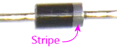
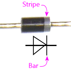
The standard convention is that the "-" end of the diode is marked
with a painted stripe - a ring around the cylinder. It's usually a
white stripe to contrast with the black case, although sometimes the
ink is so thinly applied that it comes out a pale gray. You might
need a bright light to see it. I had to artificially increase the
contrast in these photos to make the stripe apparent.
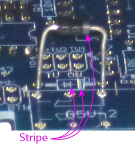
Installing in a circuit board
The circuit board install location for a diode is marked with a little
outline of the diode as seen from above when installed, showing the
cylindrical body, and lines extending on either side to represent the
wire leads. The lines extend to the solder pads where the diode is to
be installed.
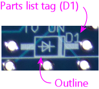
This looks very similar to the outline for a resistor, so to help
clarify that it's a diode, the outline has the schematic symbol for
a diode inside:

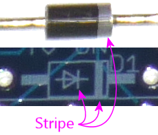
This symbol is also there as an orientation marker, so pay close
attention to it! The stripe on the diode goes on the side with
the stripe in the picture:
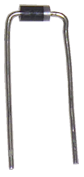
As with resistors, a diode's wire leads usually start out sticking
straight out from the body, so you have to bend each lead at a 90°
angle to fit it through the closely-spaced holes in the circuit board.
You can bend the leads by hand, or use needle-nose pliers if you want a
sharper corner, which can make for an easier fit on the board. Use
the spacing of the holes on the circuit board to determine where to
bend the leads - usually they have to bent as close to the body as
you can get.
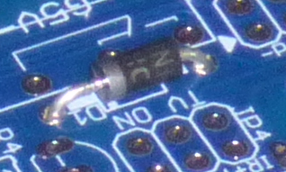
With the leads bent to fit the hole spacing in the circuit board, fit
the ends of the leads into the holes in the solder pads, then feed the
leads through until the diode is seated flat against the board. As
always, you should get it as close as comfortably possible, but don't
force it.
Be sure to orient the diode properly! Remember, the stripe painted on
the aligns with the stripe in the circuit board outline, and also with
the "bar" in the diode symbol printed on the board.
With the diode seated - and after you've double-check the orientation!
- hold the diode in place, flip the board over, and solder the leads
to the pads on the bottom side of the board. Snip the excess length
from the leads after the solder cools.
On schematics
A diode is represented by a symbol like this on a schematic:
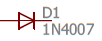
This is meant to represent the diode's one-way-valve property; the
arrow points from positive to negative, and the little bar indicates
the barrier to reverse flow.
When relating the schematic symbol to an actual diode, the key is
to line up the bar on the schematic symbol with the stripe on the
diode body.
The diode symbol on a schematic should always be accompanied by a
reference designator, usually a "D" number (D1, D2, etc), "D" for
diode. As always, this is just an arbitrary name for looking up in
the parts list and doesn't mean anything by itself.
You'll also usually see (as we do here) a part number for the diode,
in this case 1N4007. Many diodes have generic "1N" numbers,
indicating a common type of diode that's made by multiple
manufacturers to the same specs.
(If you've taken a high school physics class, you probably know the
jaded history of this symbol and how it points in the "wrong"
direction in a physical sense. During the early days of electronics,
it was believed that the charge carriers in an electronic circuit were
positively charge ions, so the convention was to draw diagrams showing
current flowing from positive to negative. It was later discovered
that the actual moving particles are electrons, but everyone agreed it
would be too confusing to change, given all of the existing literature
based on postive-to-negative current flow. So we still use those
original conventions to this day, even though everyone now understands
that the electrons are actually traveling against the arrow.
Engineers today just make the reversal mentally whenever they have to
think about the physics of it. At least they're consistent:
the same wrong-way-arrow can be found throughout electronics
symbolism, such as in the symbols for transistors and MOSFETs.)
Selection
Unlike resistors and capacitors, diodes don't have any simple "unit"
that describes them. So instead, schematics and parts list will
specify a particular diode to use, by part number.
Part numbers starting with "1N" are common, generic types of diodes
that are made by multiple manufacturers to the same specs. There are
also less common diodes manufactured for specific properties by one
company, so you might see specific manufacturer part numbers instead
of "1N" numbers as well.
In any case, use the part number to search at Mouser or another vendor
to find matching parts. It's always easiest to go with an exact
match, but in some cases, you might find cross-references where the
manufacturer says that a different part can be substituted for the
part you're looking for. These substitutions are usually listed in
tables in the data sheets, so searches on vendor sites might not turn
them up, but Google searches might. You can try search terms like
"1N4007 equivalent" if you have trouble locating the exact part
you're looking for.
